Sunday, October 15, 2023

Intrinsic Safety

Short note to Intrinsic Safety 

In the many industrial processes where flammable materials are handled, any leak or spillage may give rise to an explosive atmosphere. To protect both personnel and plant, precautions must be taken to ensure that this atmosphere cannot be ignited. The areas at risk are known as ‘hazardous areas’ and the materials that are commonly involved include crude oil and its derivatives, natural and man-made process gases, alcohols, dusts, carbon dust, flour, starch, grain & fibres.

At one time, pneumatic control was widely used in such environments for its inherent safety but, although much pneumatic equipment is still in use in many parts of the world, it is now seldom chosen for new instrumentation systems due to its limited capability.

Intrinsic safety is achieved with the use of a Zener Diodes which limits voltage, resistors that limit the current and a fuse to cut off electricity. Equipment or devices that may be made intrinsically safe must first be approved for use in an intrinsically safe system through a competent authority, such as the National Fire Protection Agency (NFPA), the Canadian Standards Association (CSA), Underwriters Laboratories (UL), Factory Mutual (FM), National Electric Code (NEC), and the Instrument Society of Measurement and Control (ISA).

To enable electrical equipment to be used in hazardous areas, eight different ‘explosion-protection’ techniques have been developed over the years. National or international standards and codes of practice govern each technique and define in detail how the equipment should be designed and applied. National certifying (or approvals) authorities ensure design compliance and national inspectorates (or insurance companies) vet and usually inspect each installation. The different techniques lend themselves to different applications and, for instrumentation used in process measurement and control, the two leading techniques are the use of ‘flameproof enclosures’ and ‘intrinsic safety’.

With the flameproof technique, known as ‘explosionproof’ in the USA and Canada, hazardous-area equipment is surrounded by a strong enclosure which can withstand internal explosions without igniting the external atmosphere. This technique, which has been in use for over 80 years, allows high power levels but has the disadvantages that the enclosures are heavy and expensive and must not be opened without first disconnecting the electrical circuit or obtaining a ‘gas-free certificate’ for the relevant plant area.

By contrast, in the case of the IS technique, the electrical energy in hazardous-area circuits is deliberately restricted such that any electrical sparks or hot spots that may occur are too weak to cause ignition. This is achieved by inserting an energy-limiting interface in the wiring between safe and hazardous areas. The interface passes signals in either direction as required but limits the voltage and current that can reach the hazardous area under fault conditions. It may be integral with the safe-area equipment or separate for greater flexibility. First developed in the United Kingdom between 1914 and 1916 for use in coal mines, IS came into its own for other applications in the early 1960s with the introduction of the ‘shunt-diode safety barrier’ based on the voltage-limiting, Zener diode. Since then, IS has been developed as a technique and used increasingly until it is now the preferred solution in most markets.

The main reasons for the continually increasing popularity of intrinsic safety are as follows:

·        Advances in semiconductors; allowing increasingly complex electrical operations to be carried out in hazardous areas at the low power levels permitted – typically in the order of 1 watt;

·        simple, light and inexpensive hazardous-area equipment which can be calibrated and serviced ‘live’;

·        the ability to use ordinary instrument wiring in hazardous areas instead of armoured cable and the inherent safety for personnel due to the low voltages employed.

Progressive harmonisation of standards governing the design of IS equipment, is taking place. This will allow the same product to be sold and used in many countries without any variation.

Intrinsic safety is one of the key methods used to protect electrical equipment in hazardous locations, but understanding its nuances can be challenging. In this webinar, we discuss what intrinsic safety is, the types of equipment that use this protection concept, the global requirements and standards applied, and the fundamentals for making a device intrinsically safe.

With a certified IS interface, safe-area equipment needs no certification and the user can choose or change the hazardous-area equipment within wide limits. Simple, ‘non-energy storing’ sensors need no certification.

Below trusted brand I.S detector MCP part code:

The main advantage is that it provides a solution to all problems that occur in a hazardous area regarding equipment. It prevents the cost and bulk of explosion proof enclosures, with additional cost savings as a result of the ability to use standard instrumentation cables. Additionally, the maintenance and diagnostic work can be performed without shutting down production and ventilating the work area. 

Intrinsic safety relates to three levels of protection, ‘ia’, ‘ib’ and ‘ic’ that aim to balance the probability of an explosive atmosphere, assessing the probability of whether that is an ignition capable situation that may occur. 

‘ia’  

Offers the highest level of protection and any equipment that is given this level is generally considered adequately safe for use in the most hazardous locations (Zone 0) with two faults.  

‘ib’  

This level is considered adequately safe with one fault is considered safe for use in less frequently hazardous areas (Zone 1).  

‘ic’  

This level is given for ‘normal operation’ with a unity factor of safety is generally acceptable in infrequently hazardous areas (Zone 2). 

Sunday, October 1, 2023

As-Built Drawings for Fire Detection Systems

As-Built Drawings for Fire Detection Systems

An as-built drawing is defined as a drawing created and submitted by a contractor after completing the project. Due to some specific inevitable issues arising during the construction process, the contractor brings necessary changes to the original drawings.

As-built drawings are supposed to be available to fire alarm technicians when they are on site to fix a broken fire alarm system. The drawings usually aren't available, but there is no clear single reason. Instead, there are many reasons, each of which can prevent the drawings from being available.

Long ago, as an early method of spreading the word of fire danger, people shouted "Fire!" That was a fire alarm system. Depending on the circumstances, people would run away from the fire to escape, or run toward the fire to help extinguish it.

Later, to warn people to take action, the town bell or other noisemaker was also used. That, too, was a fire alarm system.

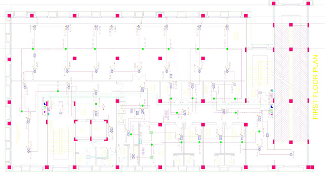
Here, the original drawings made by the design engineer have been corrected by the fire alarm installer as the installer built fire alarm system. These as-builts will be redrawn at the shop before being turned over to the building owner.

Because a building sometimes can't quite be built exactly the way it was designed, As-Built plans show the exact way the building is constructed.

When available, as-built drawings are used by architects and engineers for re-modelling or for designing new additions to the building. They're also used by service technicians when determining the layout of the fire alarm system. A fire alarm system is something that will detect fire and then to warn people of the fire.

The owner of the building project is the beginning of the planning process and the end of the planning process.

1.      Conception Plans - How the building is going to look, as conceived originally by the architect and accepted by the owner

2.      Bid Plans - Blueprints showing the architect's and engineer's pre-visualization of how a building is going to look

3.      Submittals - Blueprints showing the contractor's pre-visualization of how a building is going be constructed

4.      As-Builts - Blueprints showing what was done to make it work, specifying how the building was finally constructed, and this How-the-Building-Was-Really-Constructed --- "As-Built" --- is given back to the owner

The Conception Plans

Before a shovel is put into the ground to dig the foundations, the building is planned.

The owner either has an architect in mind, or has several architects bidding on a general idea of the design. If there are multiple architects, each one conceives of a design.

This conception includes the overall design and shows a general cost of construction for that design. These plans are the original conception plans of the building.

Bid Plans

Working with the architect, the engineer creates plans showing details of construction that make the building work.

The engineer specifies the overall structure, the materials that make up the walls, floors, ceilings, the location of electrical outlets, ventilation systems, communication systems, fire alarm systems, etc. Once the engineer is finished, the plans are ready for construction bidding.

Rather than being the final or finished blueprints, the plans become the basis for the contractor and sub-contractors to submit their bids.

These plans are the Bid Plans of the project.

Submittal Plans

The bid plans show how the completed building will look, but the plans don't show how the contractor constructs the building. Unless the make or model of equipment is specified by the engineer, the plans don't even show exactly what equipment will be used.

To show what is going to be done to make it work, the contractor and sub-contractors make changes to the bid plans, then submit the changed plans, along with the cost of construction, back to the engineers.

These plans are the Submittal Plans for the project.

As-Built Plans

Once the contractor's bid is accepted by the architect and owner, construction can begin.

The owner will want blueprints showing how the building is constructed. The problem is what was planned never is exactly what was done. In other words, even the submittal plans don't really show what was done.

For the contractor or sub-contractor to make it work:

·        Door or wall location, sometimes whole rooms may have to be different from the submitted plans

·        Location and positions of equipment or control panels may have to be different from the submitted plans

·        Wire layout or ventilation systems may have to be different from the submitted plans

The architect and engineer can't visualize every detail, and once construction is started, often the owner makes changes. To show the details of how a building is constructed, it's up to the contractor and sub-contractors to correct the plans showing what was actually done.

The person on site in charge of construction or installing the system makes corrections to the submittal drawing to create the As-Built drawings.

This is the basis for the final drawings As it was finally constructed or Built, showing:

·        The final locations for the walls, doors, window types

·        The final location of the wires

·        The final locations of the devices

·        The final location of the control panels

As-Built Drawings Made During Installation

To document the installation, at least nowadays as they build a fire alarm system, installers are the ones that produce an as-built diagram.

When troubleshooting, once the building is finished, these drawings are available to the service technician to see the layout of the fire alarm system. At least that is the intention of the NFPA Code. The NFPA shows how to design, build, and maintain a fire alarm system. The NFPA, though, is a non-profit organization. Governments use the NFPA as their law, and governments can and do enforce the NFPA Code.

Problem Getting the As-built Drawings for Troubleshooting

Architects and architectural engineers consider the as-built drawings to be very important, and they're under the impression that these drawings are always available to the people servicing the building.

In reality, for the fire alarm technician arriving on site to service the system, the as-built drawings are rarely available; there are just too many individual reasons for these drawings to be accessible:

  1. The drawings are at the shop, but the technician just doesn't have time to drive across town, find the drawings at the shop, and then return to fix the fire alarm system.
  2. The building is older so the drawings were never made in the first place.
  3. The wiring layout in the new fire alarm system is from the old system, and the as-built drawings for the old system were never made.
  4. The original drawings were made by a different fire alarm service company so the current service company doesn't have the drawings.
  5. The building has been remodeled or the system has been added to many times, but the original as-builts were never upgraded.
  6. The on-site drawings aren't available because:
    • The drawings may be on site, but:
      • They're buried in a huge pile of other drawings and it will take hours to locate the right one.
      • They're stored in a locked room that no one on site has access to.
    • They were on site at one time, but are now lost.
    • The drawings were originally turned over to the contractor, who turned them over to the owner, who didn't turn them over to the building engineer.
    • The building never had storage space for drawings - older and mid to small apartment buildings, retail stores, small office buildings, all fall under this category.
    • The drawings on site are architectural drawings and don't show how the fire alarm system was installed.
  7. The drawings that are available are now so fragile that if they're even unrolled, the paper tears apart.

Even as the building is remodeled, rarely is anyone on site keeping up the as-built drawings. When someone is keeping up these as-builts, the drawings usually only show building plans and almost never include the fire alarm system wiring.


Troubleshooting Without As-Builts

Someone once said "Experience is something you gain when things go wrong." Well, wiring issues are things that have gone wrong, and a lot of experience is gained by following the wire and fixing the problem. For fire alarm systems, one of the more common classes of trouble is problems with the wiring. The wire is hidden and goes throughout the building, so finding the source of the trouble is most of the battle.

Most of the time, as-builts of the wiring for the building are not available, or if they are available, they are obsolete because of the changes made since the original as-built diagrams were made.

It goes without saying that from time to time the fire alarm system breaks down and requires troubleshooting. For the technician, to speed up the troubleshooting process, the as-built drawings would be very helpful.

The thing is, unless there is a big change in the method of producing and distributing the as-builts to the technician, the only accessible as-built drawings available for troubleshooting will reside in the head of the service technician. These head-based as-builts will be assembled slowly over time, as the technician discovers the system wiring during regular service to the fire alarm system.

Plan Conception vs As-Built Completion

·        Before the project is started, the owner has to accept the architect's conception of the building project.

·        Before the project is bid, the architect has to accept the engineer's practical designs.

·        Before the bids are accepted, the contractor and sub-contractors have to submit plans showing what will be done.

·        As the project is completed, the contractor and sub-contractors make final corrections to the plans they had originally submitted. These corrected plans are returned up the chain to the owner and become the final As-Built Blueprints of the building.

For each building project, the planning and construction process is different, but this outline shows a general idea.

Remember As-Built drawing come along with Handover Document. End-user should verify drawing and handover documents are correct or not. Currently lots of end user accept drawing in soft copy as well as hard copy.