Saturday, December 5, 2015

Heat Detector Required for the Elevator Pit

Heat Detector Required for the Elevator Pit

Designers are always asking, "Do I need to put a heat detector in the elevator pit?"
"Are you required to install a heat detector in the bottom of the elevator shaft otherwise known as the elevator pit?".  This is a question that comes up a lot in the fire alarm industry and often has system designers and AHJs (Authority Having Jurisdiction) scratching their heads.  Another related questions is, "Why is there a sprinkler head located at the bottom of the elevator shaft?".  A sprinkler head located in the bottom of the elevator pit is in place to control the spread of fire caused by the ignition of trash and debris that has fallen through the door opening and collected over time.

There are two items that need to be present before the requirement of a fire alarm system heat detector is required.  One is the presence of an automatic sprinkler head.  NFPA 13 2010 ed. 8.15.5 states that sprinklers heads are to be installed in the top and bottom of the elevator shaft.  There are exceptions to this rule so keep in mind that not all elevator shafts will incorporate a sprinkler head.  Two is the height in which the sprinkler head is installed off the floor of the elevator pit.  ASME A17.1 states that if a sprinkler head is installed within 24" (2 feet) of the elevator pit floor, it shall be exempt from the special arrangements of inhibiting water flow until the elevator recall function has occurred.

A heat detector is required to be installed within 2' of any sprinkler head associated with shutting down the power to an elevator (NFPA 72 2010 ed. 21.4.2*). It is important to shut down the elevator power prior to the release of water from a sprinkler head since water and electronics do not mix.  This is the reason the heat detector is required to be set to a lower temperature setting and higher sensitivity setting than the sprinkler head (NFPA 72 2010 ed 21.4.1*). With that said, a heat detector is not required if the sprinkler head is located within 24" of the elevator pit floor since there is typically not any electrical components located in this area.
Elevator pit?" That part of an elevator shaft that extends from the threshold level of the lowest landing door down to the floor at the very bottom of the shaft.
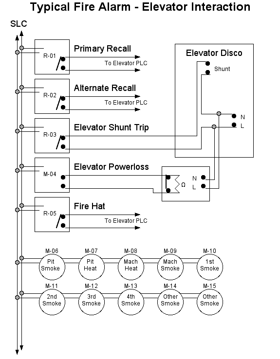
There are three common methods to shutting down the main elevator power prior to water flowing from a sprinkler head in the shaft or elevator machine room.


#1) The most economical method is to use a waterflow switch.  Upon activation, the waterflow switch would cause an alarm at the FACU (Fire Alarm Control Unit) as well as activate the shunt trip breaker causing the power to be interrupted.  Make sure you follow NFPA 72 2010 ed 21.4.3*.  This code section states that if using waterflow or pressure switches to shut down elevator power, the use of a time delay shall not be permitted.

#2) This is the most common method.  By use of a fixed temperature rate of rise heat detector located within 2' of each sprinkler head in the shaft, hoistway or elevator machine room.  The heat detector shall be set to a lower temperature than the sprinkler head and when activated, will cause an alarm at the FACU and shunt the breaker associated with powering the elevator.

#3) Use of a pre-action system.  These systems would have supplemental fire detection devices installed in the same areas as the sprinkler heads.  Make note that the detection devices should be heat detectors.  Once on of the heat detectors have been activated, it would tell the pre-action control panel through program mapping to open a valve control by a solenoid.  Once the valve is open, water would then fill the sprinkler system piping in the elevator hoistway and elevator equipment room.  At the same time, the heat detector would also trip the shunt breaker thus shutting down the elevator power.  If a fire really is present in these areas, it would eventually fuse the sprinkler head and release water to the affected area.
Keep in  mind that heat detectors are to be used for shutting down power to the elevator.


Saturday, November 7, 2015

HyperTerminal Settings For Fire Alarm Control Panels

HyperTerminal Settings For Fire Alarm Control Panels

Hyperterminal is a great way to connect to a fire alarm control panel(FACP).  It is also the preferred method to achieving a fire alarm control panels device parameters f you cannot access the program.  Simply connect your laptop to the fire alarm control panel with the appropriate cable and enter the correct values for HyperTerminal.  Once in, your laptop will mimic the FACPs screen or display.  From here you can capture the text file making it easy to store fire alarm testing reports and device parameters.

Here is a little trick if you need to know exactly what devices are on each loop.  While connected with Hyperterminal, pull off each SLC circuit one at a time.  Your laptop screen will then start to display every device on that loop as they go into trouble due to the lack of communication with the FACP loop card.  Capture the text file and your done.  You now have a simple starting plan to re-write a program if necessary.

Below are some of the HyperTerminal settings I have come across:

Notifier Fire Warden Series FACP: Includes NFW2-50 and NFW2-100
1.           Start HyperTerminal from its Start Menu icon.
2.           Give the connection a name (for example, Fire Warden) and select any icon that you’d like. Click OK to continue.
3.           In the “Connect Using” section, select the appropriate COM port that you’d like to use to communicate with the panel. Click OK after the selection has been made.
4.           Set your parameters as follows:
·                  Bits per second: 19200
·                  Data bits: 7
·                  Parity: Even
·                  Stop bits: 1
·                  Flow Control: None
5.           Click OK.
6.            You are now connected to the panel.

Fire-Lite Series FACP: Includes MS-9200, MS-9600, MS-9200UDLS, MS-9600UDLS
1.           Start HyperTerminal from its Start Menu icon.
2.           Give the connection a name (for example, Fire-Lite) and select any icon that you’d like. Click OK to continue.
3.           In the “Connect Using” section, select the appropriate COM port that you’d like to use to communicate with the panel. Click OK after the selection has been made.
4.           Set your parameters as follows:
·                  Bits per second: 19200
·                  Data bits: 7
·                  Parity: Even
·                  Stop bits: 1
·                  Flow Control: None
5.           Click OK.
6.           You are now connected to the panel.

Gamewell 600 Series FACP: Includes the IF610, IF602, IF650, IF630
1.           Start HyperTerminal from its Start Menu icon.
2.           Give the connection a name (for example, 600) and select any icon that you’d like. Click OK to continue.
3.           In the “Connect Using” section, select the appropriate COM port that you’d like to use to communicate with the panel. Click OK after the selection has been made.
4.           Set your parameters as follows:
·                  Bits per second: 2400
·                  Data bits: 8
·                  Parity: None
·                  Stop bits: 1
·                  Flow Control: Xon / Xoff
5.           Click OK.
6.           Select the pull down file menu at the top of the screen
7.           Select properties
8.           Select settings tab
9.           Set emulation to VT-100
10.        Select ASCII setup
11.        Change the line display setting to 1 milliseconds
12.        Change character display setting to 100 milliseconds
13.        Click OK twice
14.         You are now connected to the panel.

FCI E3 Series FACP:
1.           Start HyperTerminal from its Start Menu icon.
2.           Give the connection a name (for example, E3) and select any icon that you’d like. Click OK to continue.
3.           In the “Connect Using” section, select the appropriate COM port that you’d like to use to communicate with the panel. Click OK after the selection has been made.
4.           Set your parameters as follows:
·                  Bits per second: 115200
·                  Data bits: 8
·                  Parity: None
·                  Stop bits: 1
·                  Flow Control: None
5.           Click OK.
·                  You are now connected to the panel.

FCI 7100 Series FACP:
1.           Start HyperTerminal from its Start Menu icon.
2.           Give the connection a name (for example, 7100) and select any icon that you’d like. Click OK to continue.
3.           In the “Connect Using” section, select the appropriate COM port that you’d like to use to communicate with the panel. Click OK after the selection has been made.
4.           Set your parameters as follows:
·                  Bits per second: 9600
·                  Data bits: 8
·                  Parity: None
·                  Stop bits: 1
·                  Flow Control: None
5.           Click OK.
7.           You are now connected to the panel.

FCI 7200 Series FACP:
1.           Start HyperTerminal from its Start Menu icon.
2.           Give the connection a name (for example, 7200) and select any icon that you’d like. Click OK to continue.
3.           In the “Connect Using” section, select the appropriate COM port that you’d like to use to communicate with the panel. Click OK after the selection has been made.
4.           Set your parameters as follows:
·                  Bits per second: 1200
·                  Data bits: Leave Default
·                  Parity: Leave Default
·                  Stop bits: Leave Default
·                  Flow Control: None
5.           Click OK.
6.           You are now connected to the panel.


Saturday, October 3, 2015

Difference between XLPE and PVC Cables

Difference between XLPE and PVC Cables

XLPE - is cross linked polyethylene cable. 

Main Thumb rule for differentiation is that XLPE cables can be used for both HT and LT lines.
But PVC Cables can be used only for LT lines.

XLPE can withstand a higher temperature than PVC without detriment. This means that more current can be conducted for the same cross sectional area of copper. This means a big saving in cables costs. 

XLPE Cables useful properties are:-

1. Temperature resistance
2. Stress rupture resistance
3. Environmental stress crack resistance
4. Resistance to U.V light
5. Chemical resistance
6. Oxidation resistance

XLPE Cables can be useful for following applications:-

1) XLPE cables work for the working voltage of 240 V to 500 KV .
2) Conductor Material can be either Copper or Aluminum.
3) XLPE cables can be either Single Core cables or Multi core cables depending upon the number of
cores.
4) They can be Unarmoured or Strip Armoured or Wire Armoured or Tape Armoured type depending upon the presence or absence of Armour.
5) HT / LT Aerial Bunched Cables


Polyvinyl chloride Cables useful properties are :-

They are commonly abbreviated as PVC, insulated cables are widely used in various fields.
PVC's Cables are generally have following Properties:-
1. Low cost
2. Chemical resistance
3. High tensile strength
4. Better flexibility

For, electric cables the PVC is mixed up with plasticizers.
Low voltage copper conductor PVC cables are extensively used for domestic home appliances wiring, house wiring and internal wiring for lighting circuits in factories, power supply for office automation, in control.
PVC CABLES
1) Power Cables upto 1.1 KV
2) Multicore Cables upto 61 Cores
3) Sheilded instrumentation Cables
4) FRLS / FR / HR / Fire Survival Cable 

-> Electrical, mechanical, weather ability contrast table:
Properties
XLPE
PVC
1. Chemical Structure
Thermoset, pure Hydrocarbon. Non-Polar C-C or Si-o-Bonds
Thermoplastic Polar Rotosenated. C. Ci. Bond
2. Polymer Structure
Partial Crystalline
Amorphous
3. Long-term Working Temperature
90
70
4. Emergency overload
130
90
5. Highest working temperature of short circuit
250
160
6. Carrying capacity(A)
1.25a
1a
7. Dielectric constant(20,60Hz)
2.3
8
8. Cable Installation Job 
Easy due to less Wt, less Diam and Less Bending radius.
 Not Easy Like XLPE
9. Service life (year)
30
20
10. Cable diameter
0.92D
D
11. Volume resistivity(Ω·m)
1016~1018
1010-1013
12. Tensile strength(Mpa)
23
20
13. Thermal Resistivity   (Deg C/cm/watt)    
7.4
730
14. Thermal conductivity(W/m·K)
0.48
0.15
15. Dielectric loss tangent (20,60Hz)
0.0002-0.0003
0.04-0.12
16. Elongation (%)
450-600
100-400
17. The breakdown field strength (MV/m)
35-50
20-35
18.Power Factor at 20DegC X1013
-90
80
19. Low Temperature   Brittleness Deg. C
Excellent
-15
20. Moisture Penetration   Resistance
Excellent
Good
21. Water quantity (%)
<0.01
0.8
22. Oxygen index
18
30
23. Toxicity index
1.77
15.01
24. Brittleness temperature
-60
-40
25. Softening temperature
120
120
26. Resistance to acid and alkali, and climate
best
good ~ best
27. Whether containing halogen
do not contain
containing
28. Moisture Penetration   Resistance
Excellent
Good
29. Oil Resistance
Excellent
Fair
30. Solvent Resistance
Excellent
Poor
31. Acid Resistance
Excellent
Fair
32. Alkali Resistance
Excellent
Good
33. Standard
BS 5467
BS 6346

-> Toxicity index comparison table:
Gas
Gas concentration CQ(ppm)
Dangerous concentrations CQ (ppm)
Polyvinyl chloride (PVC)
Crosslinked polyethylene (XLPE)
CO
5525
1971
4000
CO2
46300
125400
100000
HCL
6173
0
500
NO2
1.5
3.6
250
SO2
3.25
1.8
400
Toxicity index
15.01
1.77


Summary: cross linked polyethylene insulation cable in the electrical performance, heat resistance, physical and mechanical properties, resistance to climate and toxicity are better than PVC insulated cable.

Reasons Why XLPE is Popular
Here are five reasons why XLPE are popular than standard wires available in the market.
  1. Excellent Mechanical and Physical Properties: XLPE has high thermal resistance and higher melting point than most standard cables found in the market. These cables possess low tan delta, high initial dielectric strength, low dielectric strength, and improved mechanical properties at high temperature. Also, XLPE resists moisture, UV light, oxidation, environmental stress, stress cracking, and rupture.
  2. Lightweight: The XLPE wire is lighter than other standard wires with a paper or lead insulation. That’s why it is more convenient to install and transport. XLPE wires are largely used in the construction industry because they reduce transportation and installation costs.
  3. Easy to Maintain: XLPE wires require lesser maintenance, when compared to other standard cables. Also, they have easy jointing and termination procedures.
  4. Used for HT and LT Lines: XLPE wires can be used for both HT and LT lines.
  5. Flexibility: XLPE wires have multiple cores, which makes them highly flexible. This added flexibility contributes to smaller bending radius as well.


Recently XLVLDPE (Cross Linked Very Low Density Polyethylene) wires have been introduced to the market.  These wires have enhanced physical and mechanical properties than regular XLPE wires. The above-mentioned factors and XLVLPDE wires depict the rising popularity of XLPE wires in the market.