Tuesday, June 15, 2021

MCP Testing

MCP Testing

Manual Call Point is a device for the manual initiation of an alarm.

Manual fire alarm activation is typically achieved through the use of a pull station (term used in USA & Canada) or call point (term used in Europe, Australia, and Asia), which then sounds the evacuation alarm for the relevant building or zone. Manual fire alarm activation requires human intervention.

Manual Call Points (MCPs) are referred to or referenced by different names in various regions worldwide like Break Glass Units (BGs), Pull Stations, Push Buttons, Alarm Points, etc.

When should a Manual Call Point be used? In the event of a fire in a building; or if there is no automatic detection activated by the installed heat & smoke detection or any other detectors; or if you discover the fire personally and if there is an emergency condition – you need to activate the Manual Call Point to trigger the Fire Detection And Alarm System (FDAS) in the building so that the system initiates the necessary notification devices and sends signals to many other third party systems (Voice Evacuation, Emergency Lighting, Smoke Control, Lifts, etc.) in the building.

🔴 Manual Call Point (MCP)
✔ Commonly used term in the UK, Europe, Middle East, and UAE
✔ Typically incorporates a break-glass or resettable element
✔ Allows manual activation of the fire alarm during an emergency
✔ Governed by EN 54 and adopted in the UAE Fire & Life Safety Code

🔴 Manual Pull Station
✔ Common term used in NFPA / North American standards; typically UL-listed
✔ Operated by pulling a lever or handle
✔ Performs the same function as a Manual Call Point
✔ Covered under NFPA 72 and acceptable under the UAE Fire & Life Safety Code

🔴 Break Glass Unit
✔ Describes the activation mechanism, not the system function
✔ Can form part of a Manual Call Point
✔ Requires breaking a glass or frangible element to operate
✔ Modern systems often use resettable (non-breakable) elements

How to Activate a Manual Call Point? There are different types of manual call points.
1. Break Glass Unit – Break the glass, and then the signal will be sent to the system
2. Pull Station – Pull the lever, and then the signal will be sent to the system
3. Break Glass with Double Action cover – Lift the cover and break the Glass
4. Pull Station with double action cover – Lift the cover and pull the lever
5. Push Button type – Push the button, and the signal will be sent to the system

There are many different types; most often, when installed for FDAS, they are installed in red housing or casing for easy identification; however, in some jurisdictions, these can be other colours for architectural aesthetical purposes. It is always important to check with the authority having jurisdiction and to ensure the MCPs are readily recognisable, easily identified and signed as per the local guidelines and regulations.

Before starting the job, take the proper work permit and inform to all the respective departments. Also, do force the respective logics or interlocks if any (like fire suppression systems activation etc).

§  Remove all the screws and remove the glass cap from MCP.

§  After removing the glass cap from MCP,  the switch inside it activates so alarm appears on Fire alarm panel and the hooter is activated.

§  Acknowledge the alarm or silence the hooter on the fire alarm panel.

§  Note down the alarm tag and descriptions from the HMI or workstation. The alarm details must match with the MCP tag number and installed location.

§  Confirm the MCP activation status from the respective graphics page. You have to visually identify the color change signals of the respective MCP on the graphics.

§  Check the + 36 Volts DC Supply on Monitor Module between terminal 1 and 2. (This is the circuit module inside the MCP).

§  Check all the wire connections on Monitor Module, the push button contact if it found loose then tighten them fully.

§  Ensure resistor leads are completely tightened on to the terminals of the circuit in MCP.

§  Clean the MCP dust by brush and cotton cloth.

§  Fix the glass cap of MCP and fix all screws. It should be fully tightened. If it is loose alarm reappears.

§  Reset the alarm signal from the Fire Alarm Panel.

§  Now MCP is working now in Normal condition.

§  Repeat the above procedure for all the remaining MCP’s.

§  Normalize the forced interlocks or logics if any.

§  Close the work permit.

Note: The mentioned voltages, terminals, circuit module names may change as per the vendor or model of the Manual Call Point.

As per UAE Fire and Life Safety Code:-
🔥 The manual call points shall be used only for fire alarm initiation. In addition, all manual call points within an occupancy shall be of similar design.
🔥 Distribution of the manual call points should be such that the travel distance should not be more than 61m to reach the nearest manual call point.
🔥 These figures are to be reduced to 25m and 16m in limited mobility areas and where processes of the area result in a likelihood of rapid-fire development.
🔥 A Manual Call Point shall be installed within 1.5 m from the exit door opening.
🔥 The manual call points shall be installed generally at the height of 1.2 m, above floor level, and in plain, accessible, well-lit, and free-hindrances places.

👉 To allow occupants to manually initiate a fire alarm signal
Understanding correct terminology helps prevent miscommunication during design, approval, installation, and inspections, especially on international projects.

If you would like to discuss further with us on MCPs and FDAS, don’t hesitate to get in touch with one of our technical experts.

Tuesday, June 1, 2021

T-Tapping in Fire Loop Line

 T-Tapping in Fire Loop Line

A fire alarm “T-Tap” is merely a parallel tap into the loop. The reason T-Tap wiring is allowed is because communications are being supervised to the device level. T-Tapping the different legs of the SLC provide multiple communications paths of the field devices and control equipment.
The answer to the question of how many T-Taps is allowed --- is "It Depends". It depends on the manufacturer and it depends on how easy the installer wants to make the system for the technician when servicing the system for the coming years. On a conventional system “T-Tap” not working.

Style 4 wiring (somewhat similar to Class B wiring), which is the data-loop or signaling line circuit (SLC), allows an unlimited number of T-Taps, at least for most manufacturers. Signaling Line Circuit (SLC), carries signals in the form of data between the panel and the input and output devices. Canada calls "Class B Level 1" "Data Communications Link (DCL) Style B". Someone called Initiating Device Circuit (IDC), its carries signals from the input devices to the panel.

Field Devices Connected to an SLC/DCL/IDC.

Input

·        Smoke Detectors

·        Heat Detectors

·        Combination Smoke/Heat Detectors

·        Pull Stations

·        Alarm and Supervisory Input Modules

Output

·        Control Relays

·        NAC Riser Modules

o   24 VDC Audible

o   24 VDC Visible

o   24 VDC Combination Audible/Visible

o   Audio for Speakers (Direct Current (DC) blocking capacitor allows 70.7 VAC 200-20KHz through) independent of other audio.

o   Firefighter’s Phone

Every device on a Signaling Line Circuit is a T-Tap for the Panel.

 
Long Star-Taps

Most fire alarm systems that use Style 4 wiring for the SLC are electronically connecting every device directly to the terminals of the fire alarm panel. Being wire nutted at all junctions, electrically the wire loop is a single pair of copper conductors. 

For all practical purposes, all devices on the loop are connected directly to the panel, and the panel can't tell the difference between home runs to each device and a single daisy chain. 

Yes, the installed wiring may daisy chain to 75 devices in a straight line, but electrically, every last one of them is connected directly to the terminals of the fire alarm panel. 

For these types of systems, the wires can be thought of as having a long star-tap. 

Later Servicing the System

The real concern with the T-Taps is with the later servicing of the system. When trying to find a ground fault or bad device. A limited number of T-Taps makes it easy to divide up the system. 
Not enough T-Taps and the technician has to guess where the wires run through the building. Too many T-Taps and the technician has to pull a lot of T-Taps apart to get an idea of where to find the faulty device or wiring. 

Manufacturer's T-Tap Limit

The manufacturers that limit the number of T-Taps have an input side and an output side to each device on the SLC. Here the panel itself is creating a map of the SLC wiring system. If there are too many t-taps, or if the ins and outs of the devices are not wired according to the installation sheets, the panel's created maps become useless for later servicing. 

How Many T-Taps

When trying to determine how many T-Taps are allowed, consult the manufacturer' installation sheets, and then decide on how easy the servicing of the system should be in the coming years.

If you still aren't sure how you manage your building / establishment loop line, feel free to get in touch with one of our experts via ssaintegrate@gmail.com. Before selecting vendor / installer check and verify they are authorized or not to execute your Fire Detection & Alarm system work. Its mandatory Fire Detection & Alarm System (Edwards, ESSER, Notifier, Autronica, Cooper, BOSCH & GST etc) commissioned by certified professional.


Tuesday, May 11, 2021

Heat Detector Testing

 Heat Detector Testing

Heat detector can be defined as an element or device that detects changes in heat or fire. If any heat (change in heat that exceeds the limits of heat sensor ratings) is sensed by the heat sensor, the heat sensor generates a signal for alerting or activating a security or protection system to extinguish or avoid the fire accidents. There are different types of heat sensors, which are classified based on different criteria such as the amount of heat withstanding capacity, nature of heat sensing capacity, and so on. Furthermore, the heat sensors are classified into different types that include analog heat sensors and digital heat sensors.

Heat detector can sense the heat (change in heat according to the features of heat detector used). But, a circuit is to be designed for activating an alarm system to indicate fire or heat change and for alerting the security or protection system. Heat detector circuit can be designed using heat sensor.

These heat detectors are mainly classified into two types based on their operation and they are “rate of rise heat detectors” and “fixed temperature heat detectors”.

Before starting the job, take the proper work permit and inform to all the respective departments. Then do force the respective logics or interlocks if any (like fire suppression systems activation etc).

§  Prior to testing of Heat detector see the LED status of the Heat Detector it should be blinking red.

§  Check the voltage of the Heat Detector, it should be + 30 Volts DC. This can be checked by the addressable base of the detector. (Digital type detector).

§  Now Heat Detector is healthy and it is ready for testing.

§  Clean the Heat Detector’s dust by cotton cloth and blower

§  Apply the heat to the Heat Detector by solo heat-detecting gun.

§  Keep applying heat for 10 seconds.

§  After 10 seconds LED status of the Heat detector is changing from steady blinking red to steady red and after that alarm appears and the hooter is activated on the fire alarm panel.

§  To silence the hooter press the acknowledge key to the Fire Alarm Panel.

§  After the alarm appears remove the heat-detecting test gun from Heat Detector.

§  Note down the alarm tag and descriptions from the HMI or Graphic workstation. The alarm details must match with the heat detector tag number and installed location.

§  Confirm the heat detector activation status from the respective graphics page. You have to visually identify the colour change signals of the respective heat detector on the graphics.

§  Reset the alarm of the Heat detector from the Fire Alarm Panel.

§  The LED status is changing from steady red to blinking red.

§  Heat Detector is now working normally.

§  Repeat the above procedure for all the remaining Heat Detectors.

§  Normalize the forced interlocks or logics if any.

§  Close the work permit.

Note: The mentioned voltages, terminals, circuit module names may change as per the vendor or model of the Heat Detector. Available in both 110 / 120 and 220 / 240 volt versions the Solo 423 and 424 are the professionals’ choice where cables and leads are acceptable. Unconstrained by energy availability they provide the quickest of test times and are, perhaps, most suitable for the highest temperature detectors.


Saturday, May 1, 2021

PLC Program for Alarm Security System

PLC Program for Alarm Security System

Programmable Logic Controllers (PLC) are often defined as miniature industrial computers that contain hardware and software used to perform control functions.

More specifically, a PLC would be used for the automation of industrial electromechanical processes, such as control of machinery on factory assembly lines, amusement rides, or food processing.

They are designed for multiple arrangements of digital and analog inputs and outputs with extended temperature ranges, immunity to electrical noise, and resistance to vibration and impact. Sometime engineer can get data from Fire Alarm Panel as integration.

Problem Description

Make burglar alarm system program in S7-1200 PLC for the house.

Consider one house, in this we want to arrange automatic burglar alarm security system. Alarm should be ON when any person will be detected by the motion sensor.

Problem Diagram

Problem Solution

·        We can solve this problem by using simple logic. Here we can use two sensors, one motion sensor and second window sensor. Window sensor is the loop of wires.

·        The motion sensor is designed such that when person is detected in a house or room, then the sensor will be activated (change its state to 1 or true)

·        Here important point in window sensor is that current is always passing until the breakage occurs in the glass. Hence output always true and when someone will try to break the window glass, current will not flow in the circuit.

List of Inputs/Outputs

Inputs List
§  System START :- I0.0
§  System STOP :- I0.1
§  Motion detector :- I0.2
§  Window sensor :- I0.3
§  Alarm stop button :- I0.4


Outputs List
§  Alarm :- Q0.0
 
M Memory
§  M0.0 :- Master coil.
§  M0.1 :- Alarm on condition.

PLC Ladder diagram for Alarm Security System


Program Description

In this problem we will consider S7-1200 PLC and TIA portal software for programming.

Network 1:-

This network shows simple latching circuit for system ON and system OFF.

we used Normally Open (NO) contact of system START button (I0.0) and NC contact of system STOP button (I0.1) for system activation.

Network 2:-

When system is activate and motion sensor (I0.2) detects the person entry, alarm on (M0.1) condition will be ON and it will activate the alarm (Q0.0).

Normally NC contact of window sensor (I0.3) is used in parallel so in normal condition it is true. If breakage of glass or window condition is detected, window sensor (I0.3) input goes false and it will activate the alarm condition (M0.1).

Network 3:-

In this network latching circuit is used for alarm (Q0.0). If alarm condition is detected (M0.1), alarm will be ON and it can be stopped by pressing alarm STOP PB (I0.4).

Note: - Above logic is for explanation purpose only. We can implement this example by using hard wired relay logic also. S7-1200 PLC system is so costly for this simple system.

Runtime Test Cases


Wednesday, April 14, 2021

NOC & Fire License in West Bengal

 NOC & Fire Licence in West Bengal

Between 2001 and 2014, close to 3 lakh deaths were reported because of fire accidents in India, an average of 59 deaths a day. Maharashtra alone accounted for 24% of all the deaths.

35 Indians die in a fire incident daily, says the National Crime Records Bureau (NCRB) based on the 12,748 lives in 2018. 56% of the deaths were caused by home fires. As many as 7,208 fire accidents were reported from residences that year. Of the fire fatalities in 2018, as many as 4,290 were in the 18-30 age group and 3,860 in the 30-45 age group.

As per the NCRB ADSI-2019 report, there were 11,037 fire accidents reported across the country in 2019. The number of such reported fire accidents fell by around 16% compared to 2018. The decline was more steeped compared to the year earlier, which was around 2%.

The data on fire accidents in India reveals that close to 3 lakh people lost their lives in fire accidents between 2001 and 2014, averaging to 59 deaths a day.

The data on fire accidents is maintained by the National Crime Records Bureau (NCRB). The data is reported in NCRB’s yearly publication, ‘Accidental Deaths & Suicides in India’. In the NCRB report, fire accidents are categorized under the following sub heads

·        Electrical Short Circuit

·        Riot/Agitation

·        Fireworks

·        Cooking Gas Cylinder/Stove Burst

·        Other Causes

Prevention is always better than cure. Thereby, it is best to avoid Fire in the first place. Although, fire emergencies and disasters can strike anyone, anytime, anywhere. We can, at least, work towards minimizing the risks of fire occurrences. Also, prevent damage.


Where is NOC:

Fire NOC means No Objection Certificate regarding Fire Safety Equipments installation in Building as per National Building Code (NBC) norms. Fire rules are different for all types buildings, means different rules as per types, height, area of constructed building. Building NOC is permission given to a person or a company to proceed with the purchase or construction of a property. While constructing a building, an applicant must obtain a No Objection Certificate (NOC) from the appropriate government authorities. As per a government notification from 2011, an NOC from the fire and emergency services is mandatory for the local municipal authority to approve building plans.
Provisional No Objection Certificate: The Provisional No Objection Certificate is to be obtained to ensure that the new constructions meet the fire safety compliant norms. ... The Occupancy Certificate is to be obtained before occupying the building and after the construction of the building is complete.

Establishments are categorized as A, B and C depending on the operational areas of the high-risk building, among other aspects. The classification is herewith specified for your reference:

Class A – refers to buildings above the height of 14.5 meters or more than 5000 cubic meters.

Class B – refers to high-risk buildings with a minimum height of seven meters and a maximum of 14.5 meters, with a coverage area spanning between 5000-2000 cubic meters.

Class C – refers to buildings below the height of seven meters or below 2000 cubic meters.

Where is Fire License 

On 23.09.19 The Mamata Banerjee government decided to slash fire-licence fees across categories by 92% after complaints emerged that the fees fixed in 2017 were too high for small traders and institutions.

“The chief minister was receiving complaints regarding the fire-licence fee during district review meetings. She had set up a committee to look into the issue. The fee is being cut down by 92%. The chief minister had promised and she delivered,” said Amit Mitra, state finance minister, at Nabanna.

Fire licence for the first category — which includes residential buildings and schools and other educational institutions up to the height of 14.5m — was fixed at Rs 4.35 per square metre and there will be no minimum amount for obtaining the licence.

Similarly, the fire licence for the second category —which covers hospitals, nursing homes and guest houses — has been cut down to Rs 6.52 per square metre

The fee for the third category — which includes ports, airports, offices and shopping complexes — was fixed at Rs 8.70 per square metre

The government decided to cut down the licence fee for the fourth category, under which licences are given to hazardous units such as fire-cracker units, to Rs 13.05 per square metre.

Fire license is obtained for forming new establishments, where the purpose of the formation is to pursue the manufacture and storage of dangerous and hazardous inflammable items. An applicant from the Northern part of Bengal must apply for availing the license at the Office of the Director-General of Fire Services, located in Siliguri. At the same time, the application for the districts of South Bengal must be filed at the office of the Collector in the License Section of Fire Brigade Department, located at Mirza Galib Street in Kolkata. The issuance and renewal of fire license will take place at the place of receipt of application. Before heading with the other aspects of registration, here’s the address for both the locations specified above:

North Zone

Dy. Director, Fire Services,

Siliguri Fire Station Complex,

Station Feeder Road, Siliguri,

Ph.: 0353 2502222/1867

South Zone

13D, Mirza Galib Street, Kolkata – 700 016,

Ph.: 033 22252222-8

The following documents must be attached with the application:

·                Two copies of the Site Plan of warehouse/workshop drawn to a scale of 1 cm: 1 meter.

·        A statement depicting the name and maximum quantity of hazardous materials to be maintained and/or processed in the premises.

·        A statement depicting particulars of fire services, which includes the number of full-time fire personnel and their qualifications, names of fire prevention and fire safety appliances in the building.

·              A statement providing the structure and nature of occupancy within the proposed warehouse/workshop.

·                   Fire Safety Certificate (if the building norms mandate this requirement).

The applicant has to submit the following documents while applying for the fire safety certificate:

·        Two copies of the architectural layout signed by the owner/occupier and the architect. The sketch must comprise of a site plan, key plan, floor-wise plan, section plan, proof plan and floor wise area statement.

·        Plan of the building with its occupancy and use.

·        Structural Plan.

·        Ownership/tenancy documents.

Fire Safety certificates are issued to ensure that the buildings are built and maintained with essential safeguards, so that fire accident of any kind is abated. This includes all high rise buildings greater than the height of 14.5 meters.

·        The application for fire certificate (for North Bengal and South Bengal applicants) must be made to the same address as that of fire license.

The fire safety certificate must be renewed upon expiry. Renewal of certificate prompts the requirement of the following documents:

·        Copy of Checklist against FSR (Fire Safety Registration) issued by the concerned personnel.

·        Copy of the endorsed Fire Safety Certificate (FSC).

To renew a fire certificate visit the official government website rendering these services. The procedure for the same is as follows:

Step 1: First things First

The applicant must first visit the concerned website; here is the link for the same https://eservices.wb.gov.in/portal/web/guest/application-for-granting/renewal-of-fire-license

Step 2: The Renewal Option

Select the option “Application for renewal of fire safety certificate” from the e-services tab on the left-hand side of the page.

Step 3: Log in

Login into the portal by providing the username and password of the user.

Step 4: Save/submitted FSR

The applicant must now choose the option “Work on Saved/Submitted FSR.”

Step 5: Mode of Submission

Choose the option “Submitted in online mode,” to work on the applications submitted online.

Step 6: Apply Online

From the “View details” option, select the option “Apply online” to open the form of “Application for Renewal of Fire Safety Certificate.”

Step 7: Edit

The page will direct to a form which is auto-filled based on the data previously entered by the applicant. The applicant can start editing by clicking the “Edit” button. After doing so, click the “Save and Next” option to proceed to the next stage.

Step 8: The Final Act

The following page, which includes a mere verification of the documents and the data uploaded by the applicant, will effectively conclude the proceedings. Click the “Save and Submit” option to save the e-form. The applicant may choose to take a print of the submitted application.

After the applicant submits the e-form, it will be automatically addressed to the concerned Department/Directorate, who in-turn will get on with the renewal process. The applicant will receive the Unique Identification Number (UIN) for future references.

The renewed certificate will be valid for a year from the date of renewal.

Tracking of Applications

To track the application status, follow the below procedure:

Step 1: Website

All major statutory processes are processed through the website, which is the same in this case. The applicant may initiate the process of status-check by visiting the same website as specified above.

Step 2: Saved/Submitted FSR

As a three-fold procedure, click on “Work on Saved/Submitted FSR,” and choose the option “Submitted Application.” Now, choose the option “Submitted in online mode” among the options provided.

Step 3: View Submitted

Now, click on the option “View Submitted Application”. Track the status by selecting the option “View Detailed Status.”

How does it get processed?

Here’s an overview of the procedures pursued by the department.

Step 1: Address to DFO

The application, upon its submission, will reach the respective DFO.

Step 2: Passing it on

The DFO will in-turn forward the same to the Head Assistant after assigning an inspecting officer.

Step 3: Preparation of Manual File

The Head Assistant formulates a manual file and addresses the application to the respective inspecting officer.

Step 4: Inspection and Reporting

The Inspecting Officer receiving the application will inspect the building after intimating the applicant of the date of inspection. Based on the inspection, the concerned officer will prepare a report.

Step 5: Recommendation  

The inspector will then state his/her views and recommend the renewal on finding that the building has adopted fire and life safety measures on par with the National Building Code and applicable building by-laws stated by the local municipal authorities.

Step 6: Back to the DFO

The concerned inspecting officer will forward the report to the DFO.

Step 7: Issue of Certificate

The DFO will issue the renewal certificate on finding that the safety measures found by the inspecting officer are concurrent with the requirements. In case of any discrepancies, the DFO will address the application to the Deputy Director, who will examine the details and forward it to the Director. Now, in this case, the Director will be in charge of issuing the renewed Fire Safety Certificate.

High-Risk Classification

Section 2 of the West Bengal Fire Services Act has categorized the following buildings into the high-risk category:

  1. Building or part of a building utilized for maintenance, handling, manufacturing or processing of highly combustible or explosive materials or products which are prone to fire incidents.
  2. Building or part of buildings utilized for maintenance, handling, manufacturing or processing of materials or products which may trigger toxic fumes or result in an explosion.
  3. Building or part of buildings utilized for manufacturing or processing of materials or products by making use of highly corrosive or noxious alkalis, acids or other liquids/chemicals which has the potential to cause an explosion or produce toxic, irritant or corrosive fumes or gases.
  4. Building or part of a building utilized for maintenance, handling, manufacturing or processing of materials producing explosive mixtures of dust, which may risk the splitting up of such materials into fine particles due to spontaneous ignition.
  5. Building or part of a building utilized for storage, when pressurized with a specific percentage of acetylene, ammonia, carbon-di-oxide, chlorine, hydrogen, methyl oxide, phosgene, sulphur dioxide, illuminating and natural gases or gases of any other kinds which has the potential to explode or emit toxic or cryogenic fumes or gases.
  6. Building or part of buildings utilized for the maintenance and handling of hazardous and highly flammable liquids and liquefiable gases.
  7. Building or part of a building utilized for maintenance and handling of hazardous substances other than liquids, which includes wool and cotton.
  8. Building or part of a building meant for the manufacture of ammunition and fireworks.
  9. Building or part of a building meant for the manufacture of artificial flowers and synthetic leather.
  10. Building or part of a building constructed as a housing complex with more than eight dwelling units.
  11. Building or part of a building of an underground structure.
  12. Building or part of a building utilized as a power generation and distribution centre, transformer house, industrial switch-gear room, major electrical installation or telephone exchange.
  13. Building or part of a building utilized as airport terminal/hangers, railway station, car shed and yard.
  14. Building or part of a building constructed as a hotel, restaurant, club with bar facilities, parlour with sauna-bath facilities, guest-house and dharmasalas.
  15. Building that can capacitate multiple persons.
  16. Building or part of a building meant for public entertainment and assembly.
  17. Building or part of a building constructed as a hospital, nursing home, sanatorium or laboratory.
  18. Building or part of a building utilized as library, museum or archaeological/research centre.
  19. Building or part of a building utilized as shopping complex, market, Katra or a fire-work outlet.


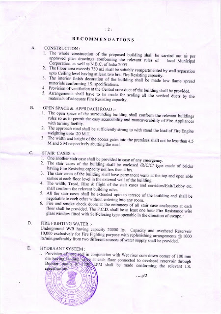
This is just an example ☝☝☝☝