Fire and Smoke Damper Installation Testing Maintenance
Dampers
are located in ductwork and ceiling cavities. Should fire break out, they're
designed to close, and so suppress the spread of smoke and fire throughout the
building.
Fire, smoke, and combination fire/smoke dampers are crucial pieces of equipment used to reduce the spread of fire and smoke throughout a building. For an overview of the basics on fire and smoke dampers refer to this newly developed fact sheet. As with all fire protection and life safety equipment, fire and smoke dampers must be properly inspected, tested, and maintained to ensure that they will operate when needed.

The
2015 Edition of the NFC added specific requirements for the inspection, testing
and maintenance of dampers. Specifically, clause (b) was added to Sentence
2.2.2.4.(5). Which now reads:
Fire
dampers, smoke dampers, combination smoke/fire dampers and fire stop flaps
shall be
a)
inspected at intervals not greater than 12 months to ensure that they are in
place and not obviously damaged or obstructed, and
b)
tested in accordance with NFPA 80, “Fire Doors and Other Opening Protectives.”
The NFC now requires that dampers be visually inspected every year and tested in accordance with NFPA 80.
NFPA 80
requires that all access panels be labelled “Fire Damper” with minimum 1”
letters. While NFPA 105 requires that all access panels be labelled “Smoke
Damper” with minimum ½” letters. Neither Standard specifies a requirement for
combination fire/smoke damper.
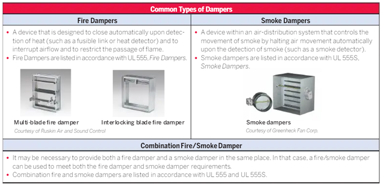
Fire Dampers
Chapter 19 of NFPA 80, Standard for Fire Doors and Other Opening Protectives, provides the ITM requirements for fire dampers.
Operational Test
An
operational test is performed (typically by the installation personnel) right
after the damper is installed to confirm the following:
·
Damper fully closes.
·
There are no obstructions to the operation of the
damper.
·
There is full and unobstructed access to the
damper.
·
For dynamic dampers, the velocity in the duct is
within the velocity rating of the damper.
·
All indicating devices are working and report
correctly.
· The fusible link (if equipped) is the correct temperature classification and rating.
Acceptance Testing
An acceptance test is a test of the damper that is completed by a
qualified person after the damper is installed, an operational test is completed,
and the entire heating, ventilation, and air conditioning (HVAC) system is
complete. The acceptance test is performed to confirm the following prior to
placing the entire system in service:
·
The
damper is not damaged or missing any parts.
·
If
actuated, dampers close fully upon disconnection of electrical power or air
pressure.
·
If
actuated, dampers fully reopen when electrical power or air pressure is
reapplied.
·
If
non-actuated, the damper closes upon removal of the fusible link and is
manually reset to the full-open position.
Testing must be done under maximum airflow after HVAC system balancing, unless acceptance testing is being performed for dampers with fusible links. In that case, it is permitted to turn the fan in the system off.
Periodic Testing
Fire
dampers need to be inspected and tested 1 year after the initial acceptance
test and then every 4 years, unless the dampers are installed in a hospital, in
which case they can be inspected and tested every 6 years.
During the
periodic inspection of an actuated fire damper, the following needs to be
completed:
·
Confirm that the damper is in the full-open or
full-closed position as required by the system design.
·
Visually confirm the damper moved to the
full-closed or full-open position when commanded.
·
Visually confirm that the damper returns to the
original operating position as required by the system design.
During the
periodic inspection of a non-actuated fire damper, the following needs to be
completed:
·
Confirm
the fusible link is not painted.
·
Confirm
the damper fully closes when the fusible link is removed or activated with the
damper in the full-open position.
·
Where
equipped, confirm that the damper latches in the full-closed position.
· Confirm that the damper is returned to the full-open and operational position with fusible link installed.

Smoke Dampers
Chapter 7 of NFPA 105, Standard for Smoke Door Assemblies and Other Opening Protectives, provides the inspection, testing, and maintenance requirements for smoke dampers, which are outlined below. Smoke dampers that are part of a smoke control system need to be inspected and tested in accordance with NFPA 92, Standard for Smoke Control Systems.
Operational Test
An operational test is performed after the damper is installed and after
the building’s heating ventilation and air conditioning (HVAC) system has been
fully balanced to confirm the following:
·
Damper
fully closes under both the normal HVAC airflow and non-airflow conditions.
·
There
are no obstructions to the operation of the damper.
·
There
is full and unobstructed access to the damper.
· All indicating devices are working and report correctly.
Acceptance Testing
An
acceptance test is a test of the damper that is completed by a qualified person
after the damper is installed, an operational test is completed, and the entire
HVAC system is complete to confirm the following prior to placing the entire
system in service:
·
The damper is not damaged or missing any parts.
·
Dampers close fully upon disconnection of
electrical power or air pressure.
·
Dampers fully reopen when electrical power or air
pressure is reapplied.
Testing must be done under maximum airflow after HVAC system balancing.
Periodic Testing
Smoke dampers need to be inspected and tested 1 year after the initial
acceptance test and then every 4 years, unless the dampers are installed in a
hospital, in which case they can be inspected and tested every 6 years.
During the periodic inspection, the following needs to be completed:
·
Confirm that the damper is in the full-open or
full-closed position as required by the system design.
·
Visually confirm the damper moved to the
full-closed or full-open position when commanded.
· Visually confirm that the damper returns to the original operating position as required by the system design.
Combination Fire/Smoke Dampers
Combination Fire/Smoke Dampers need to meet the requirements for both fire dampers and smoke dampers when it comes to ITM.
Documentation
All
inspections and tests of fire, smoke, and combination fire/smoke dampers need
to be documented and maintained for at least three test cycles. These documents
need to include the following:
·
Location
of the damper
·
Date(s)
of inspection
·
Name
of the inspector
·
Deficiencies
discovered, if any
· Indication of when and how deficiencies were corrected, if applicable
Maintenance
Proper maintenance of fire, smoke, and fire/smoke dampers is crucial to ensure that they remain operational. If a damper is found to not be operational, repairs need to be completed without delay and a periodic test must be completed after the repair is completed to ensure the damper’s operation. All exposed moving parts of the damper need to be lubricated as required by the manufacturer and any reports of an abrupt change in airflow or noise from a duct system needs to be investigated to ensure that it is not related to the damper operation.
Proper inspection, testing, and maintenance of fire, smoke, and fire/smoke dampers ensure they are installed and operating properly in the event of an emergency. For more information about the basics of fire, smoke, and combination fire/smoke dampers, write us ssaintegrate@gmail.com
Manufacturer’s Instructions – ITM Recommendations
Some manufacturers may have additional ITM recommendations. For example, Price Industries recommends “cycling all motorized fire and smoke dampers a minimum of once every 6 months”. It’s important to review the installation, operational and maintenance instructions for any additional ITM activities.

INSTALLATION AND OPERATION INSTRUCTIONS – PER
ULC-S112
ULC-S112 Section 14 outlines the installation and operating instructions. (Note that ULC-S112.1 also has similar requirements with some variations which are not provided here). The most notable requirement, in both standards is that a copy of the installation and operating instructions are required to be provided in each shipping container.
The instructions are required to specify all of the following:
·
The type of wall or partition (masonry or gypsum
wallboard) or floor, as applicable.
·
The clearances required for expansion of the fire damper,
as applicable.
·
The type and thickness of the sleeve material when the
sleeve is field assembled.
·
The type and size of fasteners and the spacing of the
fasteners used in attaching the fire damper frame to the sleeve (when a sleeve
is to be used and is to be field supplied), and perimeter mounting angles to
the fire damper frame or the sleeve.
·
The specified means of sealing the damper to ductwork or
damper frame, or both, if applicable.
·
The length of the sleeve or frame extending beyond the
wall or floor opening.
·
The type of material, size, thickness, and minimum
wall/floor overlap of the perimeter mounting angles, and whether or not they
are to be welded (or fastened using other means) to each other at the corners.
·
That the connecting ducts shall not be continuous, and
shall terminate at the sleeve or frame.
·
The type of duct-sleeve connections (see Figure 1 and
Section 12, Duct Impact Test) when sleeve thickness less than 1.6 mm steel is
used.
·
Information on connecting the actuator to the power
(electric or pneumatic) supply.
·
Any other specific features required for the installation
and operation.
For
multiple assembly of the dampers, the instructions shall also specify:
·
The method of attaching individual sections together.
·
When any mullions are required, their materials, sizes,
locations, and the method of attaching them to the dampers.
·
The maximum size of the multiple assembly that may be
assembled.
· The maximum size of the individual sections that may be attached together.
A copy of
the installation and operation instructions should be included in the buildings
fire safety plan for each type of damper, along with the initial testing and
acceptance documentation. The owner should have documentation including at
least the following: location of the damper, model number, date of
installation, hourly rating, mounting position, size, leakage rating, maximum
velocity, maximum pressure, actuator type, power source, status switch, sleeve
construction, access/equipment requirements, any additional notes. This
documentation provides information for the ongoing ITM requirements, damper
replacement, or building renovation.
We provide certified fire door installation services, ensuring that your property meets the highest safety standards. Our team of qualified professionals handles the installation of fire doors with precision and compliance to all relevant regulations and certifications. We focus on delivering quality workmanship, ensuring that each fire door is properly fitted and performs effectively in the event of a fire. Our services include assessing your needs, selecting appropriate fire doors, and completing the installation to guarantee optimal protection and safety for your building and its occupants. If you're interested in learning more about certified fire door installer, we invite you to visit this page where you'll find a wealth of resources, including articles, guides, and case studies.
ReplyDeleteWe Have best electrical contractors in lower mainland.Our experience and quality of work represent who we are our and that’s the reason we have represented clients for different projects in our work. Our crew is highly skilled and professional to understand customer needs. Also, we come up with a budget that’s reasonable for the customer and can get the best work out of it. Our company is fully licensed and bonded and all our crew is insured and WCB covered. Fourteen Electrical Ltd. It is a crew of certified electricians that provide customers with all over Lower Mainland and Fraser Valley area.
ReplyDeletelower mainland electrician
Best electrician in Surrey
Certified electricians
rewiring services in lower mainland
best electrical wiring contractor lower mainland
wiring service lower mainland
electrical wiring services lower mainland
best electrical services surrey
electrical services in surrey
best electrical services lower mainland
electrician services lower mainland
best electrical contractors in surrey
Commercial wiring services lower mainland
commercial security system installation lower mainland
residential electrician surrey bc
Discover the Few Volumes of Treaties Book Online to gain insights into historical agreements and their lasting impacts on society and governance.
ReplyDeleteGet access to the best electrical services surrey, delivering superior solutions for residential and commercial electrical needs.
ReplyDelete