Showing posts with label Smoke Detector. Show all posts

Sunday, March 16, 2025

Fire Rated GPO Box

Fire Rated GPO Box 

Every year, over half of accidental domestic fires in the INDIA are caused by electricity.  Most of these are caused by electrical products, either through misuse or faults. Electric Fire origin on account of electric short circuit, overheating, overloading, use or non standard appliances, illegal tapping of electrical wires, improper electrical wiring, carelessness and ignorance etc.

A fire rated detector junction box typically adheres to standards like BS 6387 (British Standard) which specifies testing categories for fire resistance, including "C" for fire alone, "W" for fire and water, and "Z" for fire with mechanical shock, ensuring the box maintains electrical integrity during a fire for a designated period, usually measured in minutes depending on the specific application and fire rating required.

GPO stands for general purpose outlet. GPOs mainly use as power outlets to supply power to your electronics. They are more commonly known as the power point or socket outlet. 

Maintaining fire ratings of walls even in back to back installations, Fire rated wall boxes are manufactured from robust galvabond to prevent distortion or corrosion, even under the toughest of conditions. All wall boxes should with ample knockouts for easy cable access. In addition, fixing boxes to plasterboard walls is easier than ever before thanks to clamping arms that quickly slide into place and tighten. FIRE RATED UP TO 2 HOURS.

·        We suggest Don’t overload electrical adaptors by plugging too many appliances into one socket, especially those with a high electrical current rating such as kettles, irons and heaters. Consider having additional sockets installed if you regularly rely on extension leads and adaptors - and use a registered electrician to carry out the installation work

Also follow detector mounting box/JB in same way. 96mm x 96mm box / jb is common measurement for all brand detectors. Similar as per your detection system product brand / size for Control Module, Monitor Module, MCP etc. FIRE RATED UP TO 2 HOURS.

অগ্নি-রেটেড জংশন বক্সগুলি আগুন লাগার ক্ষেত্রে অতিরিক্ত সুরক্ষা প্রদান করে , সার্কিটের অখণ্ডতা নিশ্চিত করে এবং অগ্নি বিপদাশঙ্কা, জরুরি আলো এবং সুরক্ষা সরঞ্জামের মতো গুরুত্বপূর্ণ সিস্টেমের জন্য বিদ্যুৎ সরবরাহ বজায় রাখে।

Key points about fire rated detector junction box standards:

·        Testing Categories:

Different fire exposure scenarios are tested, including high temperature flames with or without water spray and mechanical impact. 

·        Material Requirements:

Fire rated boxes are often made from materials like high-quality steel or ceramic with special insulation properties to withstand high temperatures. 

·        Functional Integrity:

The primary concern is maintaining electrical connectivity during a fire, ensuring critical circuits like fire alarms remain operational. 

Certified according to the rigorous standards of DIN 4102-12 for classes E30, E60, E90, and tested according to IEC 60331-1, this box is designed to  maintain critical services during a fire. Made of halogen-free technopolymer and steel, junction boxes offer complete customisation with single- and double-contact ceramic terminals, ceramic fuse holders, and signal  terminal blocks. Mandatory in high-traffic areas such as schools, hospitals, public buildings, industrial plants, and shopping centres, these boxes ensure the maintenance of electrical functionality even at extreme temperatures up to 1000°C for 90 minutes and 830°C for 120 minutes.

With high IP66/IP67 protection, this junction boxes retain functionality even in outdoor environments, maintaining fire resistance specifications from class E30 to E90 according to DIN 4102-12. Versions in technopolymer and steel offer practical and safe mounting and wiring solutions, with rails and rotating plates for easy installation of power terminals, signal terminals, and fuses. The classification according to DIN 4102-12 standard, which includes "E30," "E60," and "E90" categories,  ensures that electrical circuits remain operational during a fire, while the IEC 60331-1 test guarantees a performance equivalent to class PH120 of EN 50200, which is crucial for the fire resistance of electrical cables. This junction boxes are essential for the continuity of electrical supplies during a fire, ensuring the proper operation of safety devices such as fire alarm systems and emergency lighting.

Fire Resistance Testing enclosures

PH120

Insulation integrity (120-minute exposure) in accordance with BS EN 50200 & BS 8434-2 (>9300 C) with exposure to fire with water spray & mechanical shock. Rated voltage 600V rms.

IEC 331

Insulation integrity (180-minute exposure) in accordance with IEC (>7500 C) with exposure to fire with water spray & mechanical shock. Electrical system fully functional before, during and after test.

Electrical Junction Boxes for Safe & Hazardous Areas

·        Stainless Steel Enclosures & Junction Boxes

·        Aluminium Enclosures & Junction Boxes

·        GRP Enclosures & Junction Boxes

·        GRP Assembled Enclosures & Junction Boxes

·        Fire Rated Enclosures & Junction Boxes (IEC311 BS6387)

·        High Voltage Hazardous Area Electrical Enclosures & Junction Boxes

ZONE 1 HAZARDOUS AREA

Zone 1 is a classified hazardous area location in which an explosive atmosphere consisting of a mixture with air of flammable substances in the form of gas, vapour or mist is likely to occur in normal operation occasionally.

ZONE 2 HAZARDOUS AREA

Zone 2 is a classified hazardous area location in which an explosive atmosphere consisting of a mixture with air of flammable substances in the form of gas, vapour or mist is not likely to occur in normal operation but, if it does occur, persists for a short period only.

Fully ATEX certified junction boxes for hazardous area, high voltage and industrial applications can be designed and supplied customised to suit specific requirements.

Typical applications for the junction boxes include the distribution of low voltage electrical supply for power and lighting systems in onshore and offshore environments. Hazardous area junction boxes can also be configured as power supply boxes to control heat tracing systems including series heating, self-regulating and constant wattage parallel trace heating cables.

Ex d Flameproof Enclosures

Hazardous Area ZONE 1 2 21 22

Ex d flameproof enclosures provide power distribution in hazardous areas and can be configured with appropriate cable terminals to suit requirements – various sizes of electrical enclosures are available in aluminium, stainless steel and cast iron. For explosion protection types Ex e and Ex ia enclosures, a wide range of terminal and junction boxes is available are stainless or mild steel – GRP glass-reinforced polyester flameproof enclosures are also available.


Thursday, August 1, 2024

Fire and Smoke Damper ITM

 Fire and Smoke Damper Installation Testing Maintenance

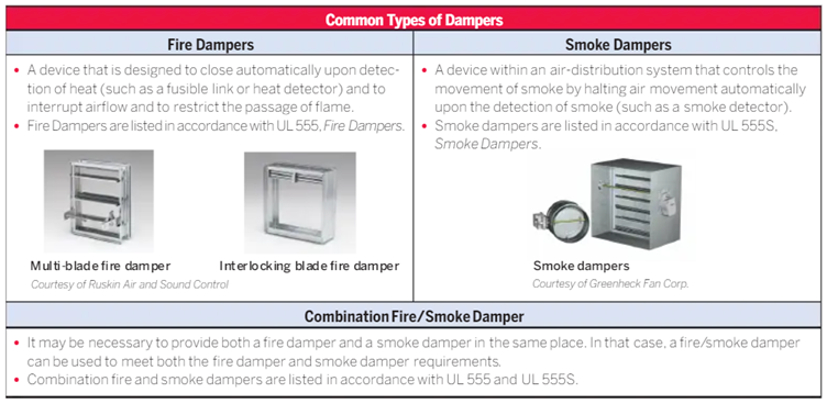
Dampers are located in ductwork and ceiling cavities. Should fire break out, they're designed to close, and so suppress the spread of smoke and fire throughout the building.

Fire, smoke, and combination fire/smoke dampers are crucial pieces of equipment used to reduce the spread of fire and smoke throughout a building. For an overview of the basics on fire and smoke dampers refer to this newly developed fact sheet. As with all fire protection and life safety equipment, fire and smoke dampers must be properly inspected, tested, and maintained to ensure that they will operate when needed.

2015 NFC ITM REQUIREMENTS

The 2015 Edition of the NFC added specific requirements for the inspection, testing and maintenance of dampers. Specifically, clause (b) was added to Sentence 2.2.2.4.(5). Which now reads:

Fire dampers, smoke dampers, combination smoke/fire dampers and fire stop flaps shall be

a) inspected at intervals not greater than 12 months to ensure that they are in place and not obviously damaged or obstructed, and

b) tested in accordance with NFPA 80, “Fire Doors and Other Opening Protectives.”

The NFC now requires that dampers be visually inspected every year and tested in accordance with NFPA 80.

NFPA 80 requires that all access panels be labelled “Fire Damper” with minimum 1” letters. While NFPA 105 requires that all access panels be labelled “Smoke Damper” with minimum ½” letters. Neither Standard specifies a requirement for combination fire/smoke damper.

Fire Dampers

Chapter 19 of NFPA 80, Standard for Fire Doors and Other Opening Protectives, provides the ITM requirements for fire dampers.

Operational Test

An operational test is performed (typically by the installation personnel) right after the damper is installed to confirm the following:

·        Damper fully closes.

·        There are no obstructions to the operation of the damper.

·        There is full and unobstructed access to the damper.

·        For dynamic dampers, the velocity in the duct is within the velocity rating of the damper.

·        All indicating devices are working and report correctly.

·        The fusible link (if equipped) is the correct temperature classification and rating.

Acceptance Testing

An acceptance test is a test of the damper that is completed by a qualified person after the damper is installed, an operational test is completed, and the entire heating, ventilation, and air conditioning (HVAC) system is complete. The acceptance test is performed to confirm the following prior to placing the entire system in service:

·        The damper is not damaged or missing any parts.

·        If actuated, dampers close fully upon disconnection of electrical power or air pressure.

·        If actuated, dampers fully reopen when electrical power or air pressure is reapplied.

·        If non-actuated, the damper closes upon removal of the fusible link and is manually reset to the full-open position.

Testing must be done under maximum airflow after HVAC system balancing, unless acceptance testing is being performed for dampers with fusible links. In that case, it is permitted to turn the fan in the system off.

Periodic Testing

Fire dampers need to be inspected and tested 1 year after the initial acceptance test and then every 4 years, unless the dampers are installed in a hospital, in which case they can be inspected and tested every 6 years.

During the periodic inspection of an actuated fire damper, the following needs to be completed:

·        Confirm that the damper is in the full-open or full-closed position as required by the system design.

·        Visually confirm the damper moved to the full-closed or full-open position when commanded.

·        Visually confirm that the damper returns to the original operating position as required by the system design.

During the periodic inspection of a non-actuated fire damper, the following needs to be completed:

·        Confirm the fusible link is not painted.

·        Confirm the damper fully closes when the fusible link is removed or activated with the damper in the full-open position.

·        Where equipped, confirm that the damper latches in the full-closed position.

·        Confirm that the damper is returned to the full-open and operational position with fusible link installed.

Smoke Dampers

Chapter 7 of NFPA 105, Standard for Smoke Door Assemblies and Other Opening Protectives, provides the inspection, testing, and maintenance requirements for smoke dampers, which are outlined below. Smoke dampers that are part of a smoke control system need to be inspected and tested in accordance with NFPA 92, Standard for Smoke Control Systems.

Operational Test

An operational test is performed after the damper is installed and after the building’s heating ventilation and air conditioning (HVAC) system has been fully balanced to confirm the following:

·        Damper fully closes under both the normal HVAC airflow and non-airflow conditions.

·        There are no obstructions to the operation of the damper.

·        There is full and unobstructed access to the damper.

·        All indicating devices are working and report correctly.

Acceptance Testing

An acceptance test is a test of the damper that is completed by a qualified person after the damper is installed, an operational test is completed, and the entire HVAC system is complete to confirm the following prior to placing the entire system in service:

·        The damper is not damaged or missing any parts.

·        Dampers close fully upon disconnection of electrical power or air pressure.

·        Dampers fully reopen when electrical power or air pressure is reapplied.

Testing must be done under maximum airflow after HVAC system balancing.

Periodic Testing

Smoke dampers need to be inspected and tested 1 year after the initial acceptance test and then every 4 years, unless the dampers are installed in a hospital, in which case they can be inspected and tested every 6 years.

During the periodic inspection, the following needs to be completed:

·        Confirm that the damper is in the full-open or full-closed position as required by the system design.

·        Visually confirm the damper moved to the full-closed or full-open position when commanded.

·        Visually confirm that the damper returns to the original operating position as required by the system design.

Combination Fire/Smoke Dampers

Combination Fire/Smoke Dampers need to meet the requirements for both fire dampers and smoke dampers when it comes to ITM.

Documentation

All inspections and tests of fire, smoke, and combination fire/smoke dampers need to be documented and maintained for at least three test cycles. These documents need to include the following:

·        Location of the damper

·        Date(s) of inspection

·        Name of the inspector

·        Deficiencies discovered, if any

·        Indication of when and how deficiencies were corrected, if applicable

Maintenance

Proper maintenance of fire, smoke, and fire/smoke dampers is crucial to ensure that they remain operational. If a damper is found to not be operational, repairs need to be completed without delay and a periodic test must be completed after the repair is completed to ensure the damper’s operation. All exposed moving parts of the damper need to be lubricated as required by the manufacturer and any reports of an abrupt change in airflow or noise from a duct system needs to be investigated to ensure that it is not related to the damper operation.

Proper inspection, testing, and maintenance of fire, smoke, and fire/smoke dampers ensure they are installed and operating properly in the event of an emergency. For more information about the basics of fire, smoke, and combination fire/smoke dampers, write us ssaintegrate@gmail.com

Manufacturer’s Instructions – ITM Recommendations

Some manufacturers may have additional ITM recommendations. For example, Price Industries recommends “cycling all motorized fire and smoke dampers a minimum of once every 6 months”. It’s important to review the installation, operational and maintenance instructions for any additional ITM activities.

INSTALLATION AND OPERATION INSTRUCTIONS – PER ULC-S112

ULC-S112 Section 14 outlines the installation and operating instructions. (Note that ULC-S112.1 also has similar requirements with some variations which are not provided here). The most notable requirement, in both standards is that a copy of the installation and operating instructions are required to be provided in each shipping container.

The instructions are required to specify all of the following:

·        The type of wall or partition (masonry or gypsum wallboard) or floor, as applicable.

·        The clearances required for expansion of the fire damper, as applicable.

·        The type and thickness of the sleeve material when the sleeve is field assembled.

·        The type and size of fasteners and the spacing of the fasteners used in attaching the fire damper frame to the sleeve (when a sleeve is to be used and is to be field supplied), and perimeter mounting angles to the fire damper frame or the sleeve.

·        The specified means of sealing the damper to ductwork or damper frame, or both, if applicable.

·        The length of the sleeve or frame extending beyond the wall or floor opening.

·        The type of material, size, thickness, and minimum wall/floor overlap of the perimeter mounting angles, and whether or not they are to be welded (or fastened using other means) to each other at the corners.

·        That the connecting ducts shall not be continuous, and shall terminate at the sleeve or frame.

·        The type of duct-sleeve connections (see Figure 1 and Section 12, Duct Impact Test) when sleeve thickness less than 1.6 mm steel is used.

·        Information on connecting the actuator to the power (electric or pneumatic) supply.

·        Any other specific features required for the installation and operation.

For multiple assembly of the dampers, the instructions shall also specify:

·        The method of attaching individual sections together.

·        When any mullions are required, their materials, sizes, locations, and the method of attaching them to the dampers.

·        The maximum size of the multiple assembly that may be assembled.

·        The maximum size of the individual sections that may be attached together.

A copy of the installation and operation instructions should be included in the buildings fire safety plan for each type of damper, along with the initial testing and acceptance documentation. The owner should have documentation including at least the following: location of the damper, model number, date of installation, hourly rating, mounting position, size, leakage rating, maximum velocity, maximum pressure, actuator type, power source, status switch, sleeve construction, access/equipment requirements, any additional notes. This documentation provides information for the ongoing ITM requirements, damper replacement, or building renovation.


Monday, January 15, 2024

FIRE WATER SUPPLY CHECKLIST

 FIRE WATER SUPPLY CHECKLIST

pROJECT INFORMATION

Project name:


Prepared by:


Checked by:


Date:


general notes

ü

N/A

Description

Remarks

Calculations shall be prepared before any design work


After selecting the Mechanical capacity for equipment, electrical data has the first priority and to be handed over to electrical Department


All architectural plans shall be revised form Mechanical point of view as soon as it is received from the Architect.


All requirements, Design stages shall be according to the prepared calculations


Shaft coordination shall be done with other MEP systems.


mep Requirements CHECKLIST

ü

N/A

Description

Remarks

Fire Water tanks Location and Capacity


Fire Water Tank as per QCD requirements


Fire water tank is 2 compartment


Type of the tanks shall be specified (GRP, Concrete, Sectional) means of access, proper ventilation, equalizing valves, overflow pipe, vents, water level indicator and drainage system. Fire tanks shall  be  provided  with  complete  appurtenances  for  maintenance  purposes,  drains,  overflow  pipe, water level indicator, tank access, vents, etc. Ensure the tank has two equal compartments, all pumps are taking suction from both tank and each pump can be isolated for testing. 


Fire Water tanks & Fire Pump room


Mechanical Pump room shall have as a separate detail with scale of 1:50


Fire Pump room area to be carefully determined according to QCD requirements and the equipment inside (Main electric pump, diesel pump, and jockey pump, bulk tank, etc.…)


Tank compartments served by the pump room shall have a common wall


 Pump room level shall be lower than the Water tank by 20 cm minimum (for tank drainage).


Clear height between the water level and the pump room bottom of slab 1 m minimum (for access door and overflow line).


Pump room shall have double leaf door opening to outside.


Filling line for Firefighting tanks shall have the same size as KAHRAMAA tie in Pipe.


Fire tanks shall have the following:

·        Drain pit ( usually 600X600X200mm)

·        Suction Pipe c/w anti-vortex plat

·        Tank drain

·        Tank Over flow

·        Filling line (c/w float valve and shall be near to the access opening)

·        Vent pipe

·        Level indicator

·        Test and drain pipe


Dimension of the room to verify adequate housing of the fire pump and related fittings, valves, headers and related equipment complying with NFPA 20 & 22. 


Sprinklers inside the fire pump room (if installed below ground level) and shall be rated as Extra Hazard Group 2.


Sequence of operations for the fire pump and Schedule of Equipment


A  testing  line  shall  be  provided  with  flow  meter  and  isolating  valve.  Provide details of each component.


Provide a pump room layout with section and elevation detail relative to the fire water tank. Ensure at least 0.8 meter clearance in every side of the pumps for maintenance work space.


Ensure that distance between pump flange and suction elbow/tee flange is greater than 10 diameter as per NFPA 20.


Provide bulk tank calculation for diesel pump.


ü

N/A

Description

Remarks

Plan and shafts requirements


Check ZCS and risers location.


DETAILED DESIGN CHECKLIST

ü

N/A

Description

Remarks

Pipe Materials


Underground main piping shall be HDPE.


Exposed pipes and pipes running inside shafts shall be black steel


Cover page


As per FF cover page file


Legend and Symbols shall be modified to contain only items in the project.


Notes Must be read Carefully to match the project.


Technical schedule shall be prepared for All projects, showing:

1-fire tank schedule indicating the following: area, effective height, volume, capacity, duration, construction type (steel, concrete), location, accessories.   

2- All types of fire pumps indicating the type of pump, capacity, head and power requirements.

3-Fire Extinguishers schedule indicating the class (A,B,C,D,K) capacity (lbs./ kg / gal), type (ABC, dry /wet chemical, CO, foam or others), description (wheeled, cartridge), rating in terms of A:B:C) and tagging (i.e. FE-1, FE-2).


Standard Details

Check that all project standard details are matching and shown (sprinklers, landing valve, fire hose reel, clean agent, fire extinguisher etc...)


Check text size to be readable when printed (even the DWG. Is N.T.S)


Design Criteria

Plan

Check location of ZCS and fire risers.


Drain pipe is installed for ZCS (test and drain valve) connected to separate drain riser.


Pipe sizes shall be according to NFPA 13


Sprinklers will be distributed as per NFPA 13 with taking in consideration maximum and minimum distance between sprinkler and wall and sprinklers with each other.


Check false ceiling depth for using double layer sprinkler.


Side wall sprinkler will be installed in elevator pit, stairs and ramps.


Sprinkler will be installed in garbage chute.


Branch lines shall not exceed eight sprinklers.


For toilets area 5m2 or higher sprinkler will be installed as per NFPA13.


In case of office building or commercial building OS&Y gate valve c/w tamper switch will be installed at the entrance of office or retail.


Check ZCS components (OS&Y, CH.V, P.G, F.S, T&D valve).


Testing connection for the most remote area will be installed.


Landing valve will be taken from stand pipe riser or combined riser (before ZCS).


Landing valve is installed in order of priority :

(1) Firefighting lobby      (2) smoke stop lobby       (3) inside staircase and comply with NFPA 14.


Fire hose reel is taken after ZCS.


Fire hose reel is distributed in corridor or lobbies provided that each one cover 30m.


Alarm gong is placed at the entrance of the building and is connected to alarm check valve in fire pump room.


Fire extinguisher (dry chemical powder) is used for stores, telecom and electric rooms in floors.


Fire extinguisher (wet chemical powder) and fire blanket (4x4) ft. is used for kitchens and pantries.


ü

N/A

Description

Remarks

Clean agent Details

Details shall be prepared for ALL projects ( small and large projects)


Foam system is used for generator room and bulk tank.


FM200 is used for fire command center , main telecom ,LV (main electric) ,MV and TX rooms in case of TX in under ground


Riser Diagram

Riser Diagram shall be prepared for ALL projects (small and large projects)


Check Riser Diagram text height shall be readable (even if it is NTS)


Riser Diagram shall show all branches and shall have the same order of the plan as possible.


PRESENTATION CHECKLIST

ü

N/A

Description

Remarks

All used blocks shall be as per FF CAD standard file.


All Layers (pipes, text, leader, etc...) shall be as per FF CAD standard file.


All text shall be using Multi leader with properties as per FF CAD standard file.


All text with boundaries shall be as per FF CAD standard file.


Text size shall be read at layout as 2.5 regardless the viewport scale.


All blocks, pipes, fittings, etc... shall have a proper scaling and dimension ( plan and Schematic)


Tanks & equipment shall have tag numbers same as equipment schedule.


Submission to CIVIL DEFENCE

ü

N/A

Description

Remarks

Documents.


Cover page shall be as per FF cover page FF CAD standard files.


CAD & PDF drawing.


Elite Calculations (most demand & most remote, Hydraulic Calculation Summary & Isometric Drawings).


Clean agent calculations.


Comments reply after revision 0