Saturday, January 2, 2016

Initiating Devices – Heat Detectors

NFPA 72 Chapter 5 Initiating Devices – Heat Detectors

This is a continuation on the series of articles about the most important requirements in NFPA 72 National Fire alarm Code Book. Chapter 4 of NFPA 72 (2016 Editions), "Fundamentals of Fire Alarm and Signaling Systems," provides the foundational rules for all fire alarm systems, covering system types, power supplies, environmental requirements, and operational monitoring. This chapter is critical for NICET Level I, II, and III exams as it outlines the core requirements for system reliability. In this articles I will discus Heat Detectors and give you the most important code requirement that you must know about for the exam.

Essential Heat Detector Concepts for NICET

  • Spacing and Layout (NFPA 72):
    • Standard Spacing: Generally 50 ft apart, with the first detector 35 ft (70% of 50) from the wall.
    • Placement: Spot-type heat detectors must be at least 4 inches from side walls.
    • Peaked Ceilings: The first row of detectors must be located within 3 ft of the peak.
    • Solid Joists: On joist construction, spacing at right angles to joists is often reduced to 50% of the listed spacing (e.g., 25 ft).
  • Types of Heat Detectors:
    • Fixed Temperature: Activates when the ambient temperature reaches a set threshold.
    • Rate-of-Rise: Activates when the temperature increases rapidly.
    • Non-restorable: Sensing element is destroyed upon activation.
  • Testing and Inspection:
    • Test heat detectors using a heat source (hairdryer or heat gun) directed at the sensor, per.
    • Non-restorable detectors: Tested mechanically and electrically only (do not heat).
    • Maintenance: Spot-type detectors must be tested at least annually.
  • Color Codes: A red color code indicates an "extra high" temperature classification
General Requirements  for all types of initiating devices:
·        Initiating devices shall only be installed in accessible locations.
·        Initiating devices shall be protected if they are exposed to mechanical damage.
·        A mechanical guard shall be listed for use with the detector.
·        Initiating devices shall be supported by another means besides their own conductors.
·        Initiating devices shall be installed in a manner to allow for regular maintenance.
·        Duplicate terminals shall be provided on the detectors for monitoring the wires for integrity.
·        Heat & Smoke Detectors Shall not be recces mounted unless they are listed and tested.
·        In a non required application where detectors are installed to achieve specific fire safety objective, additional detectors shall not be required throughout.
Heat Detectors General Requirement

·        Heat detectors shall be classified by the temperature of operation and marked with a color code according to the following table
Temperature Classification
Temperature Rating
Max Ceiling Temp
Color Code
Low
100-134 F
80 F
Unclolored
Ordinary
135-174 F
115 F
Uncolored
Intermediate
175-249 F
155 F
White
High
250-324 F
230 F
Blue
Extra High
325-399 F
305 F
Red
Very Extra High
400-499 F
380 F
Green
Ultra High
500-575 F
480 F
Orange
·        Heat detectors shall be marked with the listed operating temperature.
·        Spot type heat detector shall also be marked with the response time index.
·        Combination heat smoke detector shall be listed for no less than 50ft spacing.
Location of Heat Detectors
·        Ceiling mounted heat detector shall be located not less than 4 inch from side wall
·        Sidewall mounted heat detector shall be located between 4 and 12 inches from the ceiling.
·        Line type heat detector shall be mounted within 20 feet from the ceiling.
·        In a solid joist construction heat detectors shall be mounted at the bottom of the joist.
·        In beam construction detectors can be mounted on the bottom of the beam if the beams are less than 12 inches deep and less than 8 inches on center.

Spacing of Heat Detectors
Smooth Ceiling
·        Any point on the ceiling shall have a detector within 0.7 times the listed spacing.
·        Distance from a detector to a wall shall not exceed 1/2 of the listed spacing.
·        Heat Detectors Shall not Exceed their listed spacing.
·        In irregular areas spacing of heat detector is permitted to be more than listed spacing, provided that it should be within 0.7 time the listed spacing from a wall.
Beam Construction
·        The ceiling shall be treated as a smooth ceiling if the beam is less than 4″
·        When beam is more than 4″ spacing shall be no more than 2/3 of smooth ceiling spacing.
·        When beam project more than 18 inches from ceiling and more than 8 feet on center. than these pockets shall be treated as a separate areas.
Sloped ceiling
·        The first row of detector in sloped ceiling shall be within 3 ft of the peak.
·        If the slope is less than 30 degrees, detectors shall be spaced using the height at the peak.
·        If the slope is more than 30 degree, then the average slope height shall be used except the first detectors on the peak.
High Ceiling
·        On ceiling between 10 feet and 30 feet high, the spacing shall be reduced according to table below.
·        The minimum spacing shall not be less than 40% the height of the ceiling
Ceiling Height Above (Feet)
Up to and Including (Feet)
Multiply Listed Spacing By
0
10
1.00
10
12
0.91
12
14
0.84
14
16
0.77
16
18
0.71
18
20
0.64
20
22
0.58
22
24
0.52
24
26
0.46
26
28
0.40
28
30
0.34
This post should be part of your study guide for NICET Level 1 and Level 2. Please pay attention to the two tables above, they are table 5.6.2.1.1 and 5.6.5.5.1 on pages 72-39 and 72-40 respectively, make sure to label these sections. I am sure that these tables are good candidate for questions on the exam. I will discuss the requirement of smoke detectors and other initiating devices in upcoming post.  as always please let me know in the comment area below on what you think about this post and what would you like to see in future articles.
Cheers!!
  • Types of initiating devices include:
    • Manual fire alarm boxes / Manual Pull Station / Manual Call Point
    • Smoke detectors
    • Heat detectors
    • Flame detectors
    • Sprinkler waterflow detectors
    • Switches indicating actuation of fire suppression systems
    • Valve supervisory devices
    • Pressure supervisory devices
    • Level supervisory devices

Saturday, December 5, 2015

Heat Detector Required for the Elevator Pit

Heat Detector Required for the Elevator Pit

Designers are always asking, "Do I need to put a heat detector in the elevator pit?"
"Are you required to install a heat detector in the bottom of the elevator shaft otherwise known as the elevator pit?".  This is a question that comes up a lot in the fire alarm industry and often has system designers and AHJs (Authority Having Jurisdiction) scratching their heads.  Another related questions is, "Why is there a sprinkler head located at the bottom of the elevator shaft?".  A sprinkler head located in the bottom of the elevator pit is in place to control the spread of fire caused by the ignition of trash and debris that has fallen through the door opening and collected over time.

There are two items that need to be present before the requirement of a fire alarm system heat detector is required.  One is the presence of an automatic sprinkler head.  NFPA 13 2010 ed. 8.15.5 states that sprinklers heads are to be installed in the top and bottom of the elevator shaft.  There are exceptions to this rule so keep in mind that not all elevator shafts will incorporate a sprinkler head.  Two is the height in which the sprinkler head is installed off the floor of the elevator pit.  ASME A17.1 states that if a sprinkler head is installed within 24" (2 feet) of the elevator pit floor, it shall be exempt from the special arrangements of inhibiting water flow until the elevator recall function has occurred.

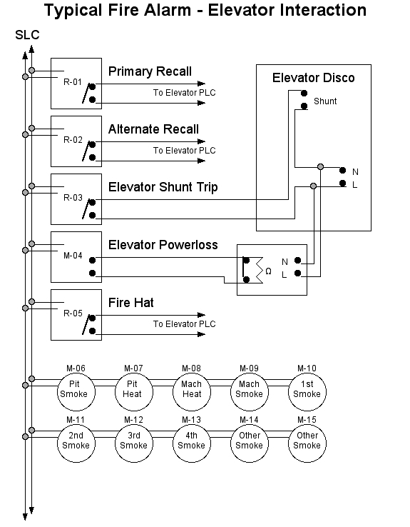
A heat detector is required to be installed within 2' of any sprinkler head associated with shutting down the power to an elevator (NFPA 72 2010 ed. 21.4.2*). It is important to shut down the elevator power prior to the release of water from a sprinkler head since water and electronics do not mix.  This is the reason the heat detector is required to be set to a lower temperature setting and higher sensitivity setting than the sprinkler head (NFPA 72 2010 ed 21.4.1*). With that said, a heat detector is not required if the sprinkler head is located within 24" of the elevator pit floor since there is typically not any electrical components located in this area.
Elevator pit?" That part of an elevator shaft that extends from the threshold level of the lowest landing door down to the floor at the very bottom of the shaft.
There are three common methods to shutting down the main elevator power prior to water flowing from a sprinkler head in the shaft or elevator machine room.


#1) The most economical method is to use a waterflow switch.  Upon activation, the waterflow switch would cause an alarm at the FACU (Fire Alarm Control Unit) as well as activate the shunt trip breaker causing the power to be interrupted.  Make sure you follow NFPA 72 2010 ed 21.4.3*.  This code section states that if using waterflow or pressure switches to shut down elevator power, the use of a time delay shall not be permitted.

#2) This is the most common method.  By use of a fixed temperature rate of rise heat detector located within 2' of each sprinkler head in the shaft, hoistway or elevator machine room.  The heat detector shall be set to a lower temperature than the sprinkler head and when activated, will cause an alarm at the FACU and shunt the breaker associated with powering the elevator.

#3) Use of a pre-action system.  These systems would have supplemental fire detection devices installed in the same areas as the sprinkler heads.  Make note that the detection devices should be heat detectors.  Once on of the heat detectors have been activated, it would tell the pre-action control panel through program mapping to open a valve control by a solenoid.  Once the valve is open, water would then fill the sprinkler system piping in the elevator hoistway and elevator equipment room.  At the same time, the heat detector would also trip the shunt breaker thus shutting down the elevator power.  If a fire really is present in these areas, it would eventually fuse the sprinkler head and release water to the affected area.
Keep in  mind that heat detectors are to be used for shutting down power to the elevator.


Saturday, November 7, 2015

HyperTerminal Settings For Fire Alarm Control Panels

HyperTerminal Settings For Fire Alarm Control Panels

Hyperterminal is a great way to connect to a fire alarm control panel(FACP).  It is also the preferred method to achieving a fire alarm control panels device parameters f you cannot access the program.  Simply connect your laptop to the fire alarm control panel with the appropriate cable and enter the correct values for HyperTerminal.  Once in, your laptop will mimic the FACPs screen or display.  From here you can capture the text file making it easy to store fire alarm testing reports and device parameters.

Here is a little trick if you need to know exactly what devices are on each loop.  While connected with Hyperterminal, pull off each SLC circuit one at a time.  Your laptop screen will then start to display every device on that loop as they go into trouble due to the lack of communication with the FACP loop card.  Capture the text file and your done.  You now have a simple starting plan to re-write a program if necessary.

Below are some of the HyperTerminal settings I have come across:

Notifier Fire Warden Series FACP: Includes NFW2-50 and NFW2-100
1.           Start HyperTerminal from its Start Menu icon.
2.           Give the connection a name (for example, Fire Warden) and select any icon that you’d like. Click OK to continue.
3.           In the “Connect Using” section, select the appropriate COM port that you’d like to use to communicate with the panel. Click OK after the selection has been made.
4.           Set your parameters as follows:
·                  Bits per second: 19200
·                  Data bits: 7
·                  Parity: Even
·                  Stop bits: 1
·                  Flow Control: None
5.           Click OK.
6.            You are now connected to the panel.

Fire-Lite Series FACP: Includes MS-9200, MS-9600, MS-9200UDLS, MS-9600UDLS
1.           Start HyperTerminal from its Start Menu icon.
2.           Give the connection a name (for example, Fire-Lite) and select any icon that you’d like. Click OK to continue.
3.           In the “Connect Using” section, select the appropriate COM port that you’d like to use to communicate with the panel. Click OK after the selection has been made.
4.           Set your parameters as follows:
·                  Bits per second: 19200
·                  Data bits: 7
·                  Parity: Even
·                  Stop bits: 1
·                  Flow Control: None
5.           Click OK.
6.           You are now connected to the panel.

Gamewell 600 Series FACP: Includes the IF610, IF602, IF650, IF630
1.           Start HyperTerminal from its Start Menu icon.
2.           Give the connection a name (for example, 600) and select any icon that you’d like. Click OK to continue.
3.           In the “Connect Using” section, select the appropriate COM port that you’d like to use to communicate with the panel. Click OK after the selection has been made.
4.           Set your parameters as follows:
·                  Bits per second: 2400
·                  Data bits: 8
·                  Parity: None
·                  Stop bits: 1
·                  Flow Control: Xon / Xoff
5.           Click OK.
6.           Select the pull down file menu at the top of the screen
7.           Select properties
8.           Select settings tab
9.           Set emulation to VT-100
10.        Select ASCII setup
11.        Change the line display setting to 1 milliseconds
12.        Change character display setting to 100 milliseconds
13.        Click OK twice
14.         You are now connected to the panel.

FCI E3 Series FACP:
1.           Start HyperTerminal from its Start Menu icon.
2.           Give the connection a name (for example, E3) and select any icon that you’d like. Click OK to continue.
3.           In the “Connect Using” section, select the appropriate COM port that you’d like to use to communicate with the panel. Click OK after the selection has been made.
4.           Set your parameters as follows:
·                  Bits per second: 115200
·                  Data bits: 8
·                  Parity: None
·                  Stop bits: 1
·                  Flow Control: None
5.           Click OK.
·                  You are now connected to the panel.

FCI 7100 Series FACP:
1.           Start HyperTerminal from its Start Menu icon.
2.           Give the connection a name (for example, 7100) and select any icon that you’d like. Click OK to continue.
3.           In the “Connect Using” section, select the appropriate COM port that you’d like to use to communicate with the panel. Click OK after the selection has been made.
4.           Set your parameters as follows:
·                  Bits per second: 9600
·                  Data bits: 8
·                  Parity: None
·                  Stop bits: 1
·                  Flow Control: None
5.           Click OK.
7.           You are now connected to the panel.

FCI 7200 Series FACP:
1.           Start HyperTerminal from its Start Menu icon.
2.           Give the connection a name (for example, 7200) and select any icon that you’d like. Click OK to continue.
3.           In the “Connect Using” section, select the appropriate COM port that you’d like to use to communicate with the panel. Click OK after the selection has been made.
4.           Set your parameters as follows:
·                  Bits per second: 1200
·                  Data bits: Leave Default
·                  Parity: Leave Default
·                  Stop bits: Leave Default
·                  Flow Control: None
5.           Click OK.
6.           You are now connected to the panel.