Saturday, March 5, 2016

Fire Survival Cable

Fire Survival Cable

Solid/Stranded (ATC/ABC) Copper conductor, insulated with specially formulated PVC/TPE/XLPE to form a core. Cores laid up together or twisted to form a pair/triad depending upon the individual requirement. Such cores/pairs/triads after laying are coated with special Fire Resistant materials and overall sheathed with special PVC/TPE/LSZH. These Fire Survival Cables are carefully tested as per IEC-60331 standards to meet the industry laid parameters.

Features:
·        High tensile strength
·        Durable
·        Water proof
·        Chemical resistant
·        Shielding with Braiding/Aluminum Mylar taping will be done overall or individually depending upon the requirement.
·        Armouring provided depending upon requirement with a extruded inner special PVC/TPE sheath, and overall sheath of special PVC/TPE.

Conductor : 
Electrolytic Grade Copper Bare / Tinned, Solid / Stranded / Annealed Flexible Conductors conforming to IS:8130:1984 or other international standard.

Fire Barrier : 
Conductor are insulated with Mica Glass Tape / silicone rubber as per requirements. Mica Tape survives temperature up to 1000°C. It is non-toxic, chemically neutral and 100% Halogen free.

Primary Insulation : 
The Insulated material may be Heat Resistant PVC / XLPE / Silicon Rubber or any other dielectric material as per customers specification.

Screening : 
Individual & Overall Shielding may be of Annealed Tinned Copper Braiding/Poly Aluminum [Thin Layer of Aluminum Foil bonded to Polyester Film] Tape with Annealed Tinned Copper Drain Wire. Braiding ATC Shield has high tensile Strength and provides better coverage in flexing application. It's also done by copper Tape or nickel copper as per specifications.

Inner Sheath : 
The Inner Sheath is applied over laid up of cores by extrusion / wrapping of thermoplastic material. The Insulation, Inner Sheath can be Normal Pvc /FR PVC / FRLS PVC / ZHFR / LSF Compound depending upon their application or specification.

Armour: 
Armour is applied over inner Sheath. It may consist of galvanized Round Steel wires or galvanized Flat Steel Strips conforming to IS: 3975. Steel wire armoured cables are suitable for direct burial. One or more copper wires can be incorporated in the armour to increase the conductivity of the Armour where it is being used as an earth return. Armour can also by steel tape / double helical steel tape or aluminum wire if client's requirement. Round Wire armoring is provided, where the calculated diameter under Armour is 13.0 m.m. above this, armoring is either round wire / steel strip as per client's requirement.

Outer Sheath : 
A final covering of PVC Compound is applied over Armouring in case of Armoured Cable or over Inner Sheath in case of Unarmoured Cable. The Color of Sheath is Black,Grey or as per customer's choice.The Outer Sheath material may be FR PVC / FRLS PVC / ZHFR / LSF as per requirement of the specification.

Standard Specifications :
ICE 331/ BS 6387 :1994, IEC 60331,
BS 6387 - CAT A,B,C,W,Z
BS 7846 - CAT F1, F2, F3
& other customized & International Standard

Fire Survival Test:
AS PER IEC-60331

Characteristics: 
* Will withstand Flame temperature of 750 degree centigrade up to 3 hours without electrical breakdown at rated voltage.
* During fire condition small quantity of toxic gases mainly, CO, CO2 are inevitably emitted. Fire Survival Cables are designed to limit these toxic gases within safety level.
* Corrosive Gases react with moisture to produce active acids which corrode metals causing extensive long term damage. Often these gases spread throughout the building through the ventilation system or within the entire installation. This is particularly damaging to electronic equipment’s and even to the exposed steel structures or even the concrete enclosed steel structures.
* Does not propagate flame. Zero Halogen Low Smoke insulation & sheath material supplied on request
This standard details the following tests to categories cables according to their fire withstand capabilities.

Resistance to Fire 950°C for 3 hours - Category C
 Performance Table
Symbol
650°C for 3 hours
A
750°C for 3 hours
B
950°C for 3 hours
C
950°C for 20 minutes
S
Resistance to Fire with Water Spray 650°C - Category W
  Performance Table
Symbol
650°C for 3 hours
W
Resistance to Fire with Mechanical Shock 950°C - Category Z
 Performance Table
Symbol
650°C
X
750°C
Y
950°C
Z

Typical Application :
These fire retardant cables Specially designed for to maintain Long-term circuit integrity during and after a fire like public address and emergency voice communication systems , fire extinguishing systems, sprinklers pumps, control panels, exit lights in high-rise building control and instrumentation services in industrial, commercial and residential complexes, hospitals, airports, malls and crowdy areas etc. data and voice transmission,CCTV, security, smoke detection and evacuation monitoring applications ,interconnection of distribution boxes and end devices, where continued functionality is required during a fire situation ,in High-temperature installation conditions.

For fire survival cable type and sizes. See below image.


Saturday, February 6, 2016

Calculate Voltage Drop in Fire Alarm Systems

Calculate Voltage Drop for Fire Alarm Systems

All electrical conductors include a small amount of resistance.  This resistance increases if the length of the conductor increases or or the conductor size decreases.  Think of blowing air through a hose. If the hose diameter decreases and or the length increases it would be harder to blow through.  You can also think of freeway traffic as resistance.  The freeway is the conductor.  The wider the freeway, the faster and smoother you travel.

As electrical current flows through the conductor it will experience a decrease in voltage between the source (starting point) and at various points along the conductor path.  Another example to look at is the voltage drop in a 1000 foot run of 16 AWG wire would be greater than that of a 1000 foot run of 12 AWG.  This is simply because a 16 AWG conductor is smaller in diameter than a 12 AWG conductor.

Fire alarm equipment LISTED to the standards of the National Fire Protection Association and Underwriters Laboratories (U.L.) is tested to determine if can operate properly at 85% of the rated nameplate voltage.  This limit was set in place to make sure the circuit can deal with a "brownout" condition or a possible voltage drop which might result from excessive resistance in the system wiring.

As required in the CFC (California Fire Code), fire alarm designers are required to prepare voltage drop calculations for the notification appliance circuits (NAC) as part of the design.  These voltage drop calculations must be included in the submittal plans and specifications.  This is to assure that the devices on the system are supplied with electrical power within the operating voltage range.

You as a designer can use several different methods to calculate voltage drop on a fire alarm circuit. One method calculates the actual voltage drop for each length of cable and device within the circuit and the other calculates the overall voltage drop.  Either method will have slightly different results but should be acceptable by your local AHJ (authority having jurisdiction)

The suggested maximum allowable voltage drop on a fire alarm circuit is 10% or the voltage drop included in the fire alarm control panel installation guide, whichever is less.
"Lump Sum Method"

Step #1)  Take the total current of the circuit.  You can achieve this figure by adding up the current draw of each device on the circuit.  This will represent "A"

Step #2)  Measure out the length of the circuit in feet.  Do not double the distance of the circuit for 2 wire loops unless you want to use a multiplying factor of 10.8 versus 21.6 (see step #3).  This will represent "L"

Step #3)  Use a multiplying factor of 21.6.  This number represents the resistivity of copper conductors.  This is a constant used in the formula.

Step #4)  Find the Circular Mils for the particular gauge wire you are using.  This can be found in the National Electrical Code (NEC) chapter 9 table 8.  #14 AWG is 4110 and #12 AWG is 6530.  This will represent "C.M".

A x L x 21.6
-------------  =   VD
    C.M.

Example

.356 x 450' x 21.6
-------------------   =   0.530 Volts Dropped
      6530

To find the percentage of voltage dropped do the following:
0.530 / 24 = 0.022
0.022 x 100 = 2.2
= 2.2% Voltage Drop

Now remember you can also perform this calculation for each individual length of wire and device on the circuit.  This is known as the "point-to-point" method.  This is a better way to perform the calculation as it gives you a chance to really break down the circuit and pin point exactly where a circuit must end do to voltage drop.  Simply use the above formula for each wire run and add the voltage drop totals for each circuit section together for the total voltage drop.  Then divide by the source voltage (in this example we will use 24VDC) and then multiply by 100 to come to a total voltage drop percentage.

For example, let’s say we have a 300-foot NAC with 10 Model GE3-24 visible-audible signaling appliances made by Gentex.

Step 1: Find the total per unit current drawn by each device on the circuit. According to the specification sheet, each strobe draws 60mA (0.060A) and each horn (Temporal 3, high setting) draws 28mA (0.028A). Adding the two together we have a total of 88mA (0.088A) per unit.
Step 2: Total the current drawn by each device on the NAC to find total current. In this case, 10 units on a single NAC gives us a total current draw of 10 X 0.088A = 0.88A. Ideally we want 10 percent above this amount for headroom, or 0.88A X 0.10 = 0.088A + 0.88A = 0.968A total current.
Step 3: Determine the to-and-from distance of the circuit. In this case, we have a 300-foot run, or 300 feet X 2 (conductors) = 600 feet total.
Step 4: Utilize a conductor properties chart to determine the resistance of the cable at the end of the circuit. An 18 AWG conductor, for example, has a resistance of 7.77 Ohms per 1,000 feet, so divide 600 by 1,000 and multiply that by 7.77 to find the actual resistance: 600/1,000 = 0.6 X 7.77 = 4.662 Ohms. A 16 AWG conductor has a listed resistance of 5.08 Ohms at 1,000 feet. Again, do the math by multiplying 5.08 by 0.6 = 3.048 Ohms.
Step 5: Determine the voltage at the end of the NAC. To do this, we use simple Ohms Law: I X R = E. We know the total current in our circuit is 0.968A (see Step 2) and we know that the actual resistance of our circuit to be 4.662 Ohms using 18 AWG and 3.048 Ohms using 16 AWG wire. Doing the math: 0.968A X 4.662 Ohms = 4.513 Volts using 18 AWG, and 0.968 X 3.048 Ohms = 2.95 volts for 16 AWG.
Step 6: Determine the actual voltage drop at the end of the NAC. To do this, begin by subtracting the voltages in Step 5 from the operating voltage at the head of the NAC: 24V - 4.513V = 19.487V for 18 AWG, and 24V - 2.95V = 21.05V for 16 AWG.
Step 7: Determine which cable size to use based on actual voltage at the end of the circuit. Use the manufacturer’s specification sheet to find out the lowest and highest voltage allowable for proper operation. In this case, our GE3-24 visible-audible signaling appliances  have an operating voltage range of 16VDC to 33VDC. As you can see, using the voltages derived in Step 6, either gauge size will work — but clearly 16 AWG would be the better choice.

Saturday, January 2, 2016

Initiating Devices – Heat Detectors

NFPA 72 Chapter 5 Initiating Devices – Heat Detectors

This is a continuation on the series of articles about the most important requirements in NFPA 72 National Fire alarm Code Book. Chapter 4 of NFPA 72 (2016 Editions), "Fundamentals of Fire Alarm and Signaling Systems," provides the foundational rules for all fire alarm systems, covering system types, power supplies, environmental requirements, and operational monitoring. This chapter is critical for NICET Level I, II, and III exams as it outlines the core requirements for system reliability. In this articles I will discus Heat Detectors and give you the most important code requirement that you must know about for the exam.

Essential Heat Detector Concepts for NICET

  • Spacing and Layout (NFPA 72):
    • Standard Spacing: Generally 50 ft apart, with the first detector 35 ft (70% of 50) from the wall.
    • Placement: Spot-type heat detectors must be at least 4 inches from side walls.
    • Peaked Ceilings: The first row of detectors must be located within 3 ft of the peak.
    • Solid Joists: On joist construction, spacing at right angles to joists is often reduced to 50% of the listed spacing (e.g., 25 ft).
  • Types of Heat Detectors:
    • Fixed Temperature: Activates when the ambient temperature reaches a set threshold.
    • Rate-of-Rise: Activates when the temperature increases rapidly.
    • Non-restorable: Sensing element is destroyed upon activation.
  • Testing and Inspection:
    • Test heat detectors using a heat source (hairdryer or heat gun) directed at the sensor, per.
    • Non-restorable detectors: Tested mechanically and electrically only (do not heat).
    • Maintenance: Spot-type detectors must be tested at least annually.
  • Color Codes: A red color code indicates an "extra high" temperature classification
General Requirements  for all types of initiating devices:
·        Initiating devices shall only be installed in accessible locations.
·        Initiating devices shall be protected if they are exposed to mechanical damage.
·        A mechanical guard shall be listed for use with the detector.
·        Initiating devices shall be supported by another means besides their own conductors.
·        Initiating devices shall be installed in a manner to allow for regular maintenance.
·        Duplicate terminals shall be provided on the detectors for monitoring the wires for integrity.
·        Heat & Smoke Detectors Shall not be recces mounted unless they are listed and tested.
·        In a non required application where detectors are installed to achieve specific fire safety objective, additional detectors shall not be required throughout.
Heat Detectors General Requirement

·        Heat detectors shall be classified by the temperature of operation and marked with a color code according to the following table
Temperature Classification
Temperature Rating
Max Ceiling Temp
Color Code
Low
100-134 F
80 F
Unclolored
Ordinary
135-174 F
115 F
Uncolored
Intermediate
175-249 F
155 F
White
High
250-324 F
230 F
Blue
Extra High
325-399 F
305 F
Red
Very Extra High
400-499 F
380 F
Green
Ultra High
500-575 F
480 F
Orange
·        Heat detectors shall be marked with the listed operating temperature.
·        Spot type heat detector shall also be marked with the response time index.
·        Combination heat smoke detector shall be listed for no less than 50ft spacing.
Location of Heat Detectors
·        Ceiling mounted heat detector shall be located not less than 4 inch from side wall
·        Sidewall mounted heat detector shall be located between 4 and 12 inches from the ceiling.
·        Line type heat detector shall be mounted within 20 feet from the ceiling.
·        In a solid joist construction heat detectors shall be mounted at the bottom of the joist.
·        In beam construction detectors can be mounted on the bottom of the beam if the beams are less than 12 inches deep and less than 8 inches on center.

Spacing of Heat Detectors
Smooth Ceiling
·        Any point on the ceiling shall have a detector within 0.7 times the listed spacing.
·        Distance from a detector to a wall shall not exceed 1/2 of the listed spacing.
·        Heat Detectors Shall not Exceed their listed spacing.
·        In irregular areas spacing of heat detector is permitted to be more than listed spacing, provided that it should be within 0.7 time the listed spacing from a wall.
Beam Construction
·        The ceiling shall be treated as a smooth ceiling if the beam is less than 4″
·        When beam is more than 4″ spacing shall be no more than 2/3 of smooth ceiling spacing.
·        When beam project more than 18 inches from ceiling and more than 8 feet on center. than these pockets shall be treated as a separate areas.
Sloped ceiling
·        The first row of detector in sloped ceiling shall be within 3 ft of the peak.
·        If the slope is less than 30 degrees, detectors shall be spaced using the height at the peak.
·        If the slope is more than 30 degree, then the average slope height shall be used except the first detectors on the peak.
High Ceiling
·        On ceiling between 10 feet and 30 feet high, the spacing shall be reduced according to table below.
·        The minimum spacing shall not be less than 40% the height of the ceiling
Ceiling Height Above (Feet)
Up to and Including (Feet)
Multiply Listed Spacing By
0
10
1.00
10
12
0.91
12
14
0.84
14
16
0.77
16
18
0.71
18
20
0.64
20
22
0.58
22
24
0.52
24
26
0.46
26
28
0.40
28
30
0.34
This post should be part of your study guide for NICET Level 1 and Level 2. Please pay attention to the two tables above, they are table 5.6.2.1.1 and 5.6.5.5.1 on pages 72-39 and 72-40 respectively, make sure to label these sections. I am sure that these tables are good candidate for questions on the exam. I will discuss the requirement of smoke detectors and other initiating devices in upcoming post.  as always please let me know in the comment area below on what you think about this post and what would you like to see in future articles.
Cheers!!
  • Types of initiating devices include:
    • Manual fire alarm boxes / Manual Pull Station / Manual Call Point
    • Smoke detectors
    • Heat detectors
    • Flame detectors
    • Sprinkler waterflow detectors
    • Switches indicating actuation of fire suppression systems
    • Valve supervisory devices
    • Pressure supervisory devices
    • Level supervisory devices

Saturday, December 5, 2015

Heat Detector Required for the Elevator Pit

Heat Detector Required for the Elevator Pit

Designers are always asking, "Do I need to put a heat detector in the elevator pit?"
"Are you required to install a heat detector in the bottom of the elevator shaft otherwise known as the elevator pit?".  This is a question that comes up a lot in the fire alarm industry and often has system designers and AHJs (Authority Having Jurisdiction) scratching their heads.  Another related questions is, "Why is there a sprinkler head located at the bottom of the elevator shaft?".  A sprinkler head located in the bottom of the elevator pit is in place to control the spread of fire caused by the ignition of trash and debris that has fallen through the door opening and collected over time.

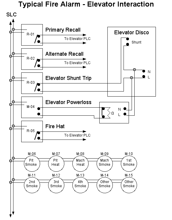
There are two items that need to be present before the requirement of a fire alarm system heat detector is required.  One is the presence of an automatic sprinkler head.  NFPA 13 2010 ed. 8.15.5 states that sprinklers heads are to be installed in the top and bottom of the elevator shaft.  There are exceptions to this rule so keep in mind that not all elevator shafts will incorporate a sprinkler head.  Two is the height in which the sprinkler head is installed off the floor of the elevator pit.  ASME A17.1 states that if a sprinkler head is installed within 24" (2 feet) of the elevator pit floor, it shall be exempt from the special arrangements of inhibiting water flow until the elevator recall function has occurred.

A heat detector is required to be installed within 2' of any sprinkler head associated with shutting down the power to an elevator (NFPA 72 2010 ed. 21.4.2*). It is important to shut down the elevator power prior to the release of water from a sprinkler head since water and electronics do not mix.  This is the reason the heat detector is required to be set to a lower temperature setting and higher sensitivity setting than the sprinkler head (NFPA 72 2010 ed 21.4.1*). With that said, a heat detector is not required if the sprinkler head is located within 24" of the elevator pit floor since there is typically not any electrical components located in this area.
Elevator pit?" That part of an elevator shaft that extends from the threshold level of the lowest landing door down to the floor at the very bottom of the shaft.
There are three common methods to shutting down the main elevator power prior to water flowing from a sprinkler head in the shaft or elevator machine room.


#1) The most economical method is to use a waterflow switch.  Upon activation, the waterflow switch would cause an alarm at the FACU (Fire Alarm Control Unit) as well as activate the shunt trip breaker causing the power to be interrupted.  Make sure you follow NFPA 72 2010 ed 21.4.3*.  This code section states that if using waterflow or pressure switches to shut down elevator power, the use of a time delay shall not be permitted.

#2) This is the most common method.  By use of a fixed temperature rate of rise heat detector located within 2' of each sprinkler head in the shaft, hoistway or elevator machine room.  The heat detector shall be set to a lower temperature than the sprinkler head and when activated, will cause an alarm at the FACU and shunt the breaker associated with powering the elevator.

#3) Use of a pre-action system.  These systems would have supplemental fire detection devices installed in the same areas as the sprinkler heads.  Make note that the detection devices should be heat detectors.  Once on of the heat detectors have been activated, it would tell the pre-action control panel through program mapping to open a valve control by a solenoid.  Once the valve is open, water would then fill the sprinkler system piping in the elevator hoistway and elevator equipment room.  At the same time, the heat detector would also trip the shunt breaker thus shutting down the elevator power.  If a fire really is present in these areas, it would eventually fuse the sprinkler head and release water to the affected area.
Keep in  mind that heat detectors are to be used for shutting down power to the elevator.